background image

Unit start/stop screen (operating modes)

Local On

Local On: The unit is in the local control mode and 

allowed to start.

Local Schedule

Local Schedule: The unit is in the local control mode 

and allowed to start if the period is occupied.

Network

Network: The unit is controlled by network commands 

and allowed to start if the period is occupied.

Remote

Remote: The unit is controlled by external commands 

and allowed to start if the period is occupied.

Master

Master: The unit operates as the master in the master/

slave assembly and allowed to start if the period is 

occupied.

To start the unit

• Press the Start/Stop button.

• Select the required Machine Mode.

• The Welcome screen will be displayed.

To stop the unit 

• Press the Start/Stop button.

• 

Confirm  the  unit  shutdown  by  pressing  Confirm  Stop  or 

cancel the unit shutdown by pressing the Back button.

The bell located in the upper-right part of the screen lights 

when any fault is detected (see section 9.1).

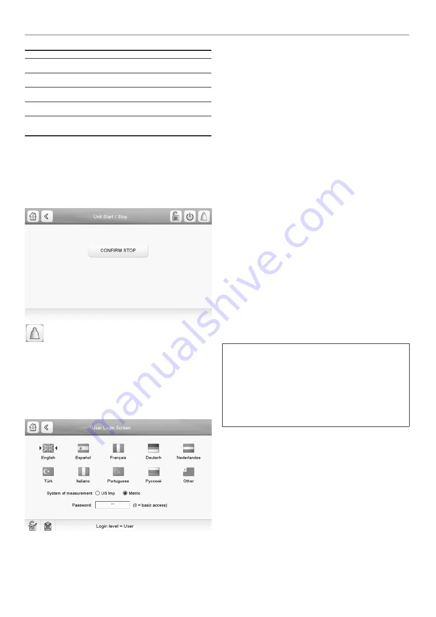
6.5 - Display settings

The User Login screen allows the user to do any of the following:


-

Select the language of the controller.


-

Change the system of measurement (imperial or metric). 


-

Gain access to more control options.

To access the User Login screen, press the Login button in the 

upper-right corner of the Synoptic screen.

Legend

1. Cursor indicating the selected language
2. Logged-in button
3. Logged-off button
4. Password dialog box
5. System of measurement: Metric/Imperial

6.6 - Display language

Display language can be modified in the User Login Screen on 

the user interface.

To change a display language

• Press the Login button to open User Login Screen.

• Select the new language of the display.

• Press the Logged-in button to save your changes or the 

Logged-off button to exit the screen without making 

modifications.

The control system allows users to add new languages to the 

control. To learn more about language customization, please 

contact your local service representative.

6.7 - System of measurement

The control offers the possibility of selecting the system of 

measurement displayed on the user interface (metric / imperial).

To change a system of measurement

• Press the Login button to open User Login Screen.

• Select the system of measurement (metric or imperial).

• Press the Logged-in button to save your changes or the 

Logged-off button to exit the screen without making 

modifications.

6.8 - User login

Only logged-in users can access configurable unit parameters. 

By default, user password is “11”. 

To log in as user

• Press the Login button to open User Login Screen. 

• Press the Password box. A dialog box appears.

• Provide the password (11) and press OK. 

• The User Login screen appears.

• Press the Logged-in button to save your changes or the 

Logged-off button to exit the screen without making 

modifications.

NOTE: You may also leave the User Login screen by pressing 

the Back button. Your changes will be saved.

Security access settings


-

User-level security ensures that only authorised users 

are allowed to modify critical unit parameters. 


-

Only logged-in users are allowed to access the  

Configuration menu.


-

It is strongly recommended to change the default 

password of the user interface to exclude the possibility 

of changing any parameters by an unqualified person.


-

Only  people  qualified  to  manage  the  unit  should  be 

familiarized with the password.

6.9 - Password change

User password can be modified in the User Configuration menu.

To change your password

• Go to the Main Menu. 

• 

Navigate to the Configuration menu (logged-in users only) 

and select User Configuration (USERCONF).

• Select the User Password box and provide the new 

password.

• 

Press OK. The User Configuration screen appears.

• Press the Save button to save your changes or the Cancel 

button to exit the screen without making modifications.

(1)

(2) (3)

(4)

(5)

6 - SETTING UP TOUCH PILOT CONTROL

12

Summary of Contents for Touch Pilot Control Series

Page 1: ...C O N T R O L S M A N U A L Original document Touch Pilot Control 19PV 550 1600 ...

Page 2: ...tart stop 11 6 5 Display settings 12 6 6 Display language 12 6 7 System of measurement 12 6 8 User login 12 6 9 Password change 12 6 10 Main menu 13 6 11 Configuration menu 13 6 12 System configuration override 13 6 13 Schedule setting 14 6 14 Web connection 15 7 DETAILED MENU STRUCTURE 16 7 1 Main menu MAINMEN1 16 7 2 Configuration menu CONFIG1 22 7 3 Alarms menu 24 8 STANDARD CONTROL OPERATIONS ...

Page 3: ...y offer for sale or contract The manufacturer reserves the right to change the design at any time without notice 9 DIAGNOSTICS 30 9 1 Control diagnostics 30 9 2 Current alarms 30 9 3 Alarms history 30 9 4 Resetting alarms 30 9 5 E mail notifications 30 9 6 Alarms description 31 10 MAINTENANCE 34 3 ...

Page 4: ...nit IMPORTANT All screenshots of the user interface provided in this manual include text in English After changing the language of the system all labels will be in the language selected by the user Please read all instructions prior to proceeding with any work Pay attention to all safety warnings The information provided herein is solely for the purpose of allowing customers to operate and service...

Page 5: ... in injury or product damage Apply all standard safety codes and practices Wear safety glasses and gloves Use the proper tools to move heavy objects Move units carefully and set them down gently 2 2 Safety precautions Only personnel qualified in accordance with IEC International Electrotechnical Commission recommendations may be permitted access to electrical components It is particularly recommen...

Page 6: ...r of mechanisms that allow the unit to operate effectively including the following 7 inch touch screen BMS connection Oil free centrifugal compressor technology Diagnostics Web connectivity e mail transmission Cooling Heating control Dry Cooler Free Cooling control optional Condenser dry cooler control optional only LEN connector provided dry cooler installed separately 3 4 Operating modes Touch P...

Page 7: ...l EXV evaporating pressure in heating mode and monitor suction pressure safeties related to the compressor operating envelope Suction pressure sensors are located on the suction piping of the circuit 4 5 Temperature sensors Temperature sensors constantly measure the temperature of various components of the unit ensuring the correct operation of the system Cooler entering leaving water temperature ...

Page 8: ...switch 2 open open closed closed 4 HARDWARE DESCRIPTION Terminal block connections Description Board Connector Remarks On Off switch SIOB 1 DI 01 32 33 Used for the unit on off control Remote mode only open unit is Off closed unit is on Heat Cool Switch SIOB 1 DI 02 63 64 Used to switch between heating and cooling Remote mode only Demand Limit Switch 1 SIOB 1 DI 03 73 74 Used to control demand lim...

Page 9: ...S Building Management System connection thanks to BACnet IP communication Legend 1 USB connector 2 Ethernet connector 3 Internal bus RS485 4 Internal bus RS485 5 Power supply connector 24 VAC 1 2 3 4 5 5 3 Touch Pilot buttons Home button Main Menu button Back button Home screen displayed Main Menu displayed Go back to the previous screen Login button Start Stop button Alarm button Basic access Uni...

Page 10: ...e Time configuration Reset Configuration Schedule Menu Pump Configuration User Configuration Holiday Menu Configuration menu Main menu General Parameters Run Times Miscellaneous Status Setpoint Table Inputs Status Temperatures Modes DC Free Cooling Status Configuration Menu Outputs Status Pressures Air Condenser Status Pump Status Reset Alarms Alarm Historic Current Alarms Alarms menu 10 ...

Page 11: ...not respond while reading the table content ACCESS DENIED Equipment controller denies access to one of the tables LIMIT EXCEEDED The value entered exceeds the parameter limit Save changes Modifications have been made The exit must be confirmed by pressing Save or Cancel HIGHER FORCE IN EFFECT Equipment controller rejects Force or Auto command Too many users connected Please try again later Too man...

Page 12: ...ows users to add new languages to the control To learn more about language customization please contact your local service representative 6 7 System of measurement The control offers the possibility of selecting the system of measurement displayed on the user interface metric imperial To change a system of measurement Press the Login button to open User Login Screen Select the system of measuremen...

Page 13: ...f user modifiable parameters such as pump configuration schedule menu etc The Configuration menu is password protected To access the Configuration menu press the Main menu button located in the upper left part of the Synoptic screen and then find and press Configuration Menu Press the field corresponding to the parameter to be modified and introduce all the necessary changes Press the Up Down butt...

Page 14: ...ine 7 Press the Save button to save your changes or the Cancel button to exit the screen without making modifications Legend 1 Selection of days for the time schedule 2 Start end of the schedule 3 Save 4 Cancel 5 Previous time period 6 Next time period Each program is in unoccupied mode unless a schedule time period is active If two periods overlap and are both active on the same day then the occu...

Page 15: ...ntrol panel clear the Keep temporary files on my computer check box and use a direct connection IMPORTANT Two users can be connected simultaneously with no priority between them Note that the last modification is always taken into account 6 14 3 Technical documentation When the Touch Pilot control is used via a pc web browser the controller allows the user to access the technical documentation for...

Page 16: ...us Pump status PUMPSTAT Miscellaneous Status Miscellaneous parameters status MSC_STAT Run Times Run times RUNTIME DC Free Cooling Status Dry Cooler Free Cooling status DCFC_STA Air Condenser Status Air Condenser status AIR_COND Setpoint Table Setpoint settings SETPOINT Configuration Menu Configuration menu CONFIG1 Displayed in English by default CAUTION Since specific units may not include additio...

Page 17: ...e unit is in Network mode the minimum value will be used compared to the status of the external limit switch contact and the demand limit switch setpoint Displayed in English by default Temperatures Menu TEMP No Name Status Default Unit Displayed text Description 1 COOL_EWT C F Cooler Entering Fluid Evaporator entering water temperature Used for capacity control 2 COOL_LWT C F Cooler Leaving Fluid...

Page 18: ...state circuit A 17 OFB_Fb open close open Contactor State Cir B Circuit Contactor state circuit B Displayed in English by default Outputs Status Menu OUTPUTS No Name Status Default Unit Displayed text Description 1 CP_A1_PW 0 to 100 0 Compressor A1 Load Compressor A1 load circuit A 2 CP_A2_PW 0 to 100 0 Compressor A2 Load Compressor A2 load circuit A 3 EXVPosA 0 to 100 0 EXV Position Circuit A EXV...

Page 19: ...mmand 3 FLOW_SW open close open Cooler Flow Switch Cooler flow switch 4 HPUMP_1 off on off Condenser Pump Command1 Condenser pump control command 5 CONDFLOW open close open Condenser Flow Status Condenser flow switch Displayed in English by default Miscellaneous Status Menu MSC_STAT No Name Status Default Unit Displayed text Description 1 m_ecopmp no yes no Eco Pump Mode Active Eco pump mode activ...

Page 20: ...FC Variable Fan Hours DCFC Variable speed fan Operating hours Displayed in English by default Air Condenser Status Menu AIR_COND No Name Status Default Unit Displayed text Description 1 oat C F Outdoor Air Temperature Outdoor air temperature 2 Dry Cooler Status Status of the Dry Cooler connected on the condenser side 3 DC_LWT C F Leaving Water Temp Leaving water temperature 4 DC_FanSt Runing Fan S...

Page 21: ... change within one minute 5 hsp1 26 7 to 63 0 80 to 145 4 37 8 100 C F Heating Setpoint 1 Heating setpoint 1 used during occupied periods 6 hsp2 26 7 to 63 0 80 to 145 4 37 8 100 C F Heating Setpoint 2 Heating setpoint 2 used during unoccupied periods 7 hramp_sp 0 11 to 11 11 0 2 to 20 0 6 1 C F Heating Ramp Loading Heating ramp loading setpoint rate at which the water temperature may change withi...

Page 22: ...o yes no Ramp Loading Select Ramp loading selection 5 off_on_d 1 to 15 1 min Unit Off to On Delay Unit Off to On delay 6 lim_sel 0 to 2 0 Demand Limit Type Select Demand limit type 7 0 None 0 None 8 1 Switch Control 1 Switch control 9 2 4 20mA Control 2 4 20mA control 10 nh_start 00 00 00 00 Night Mode Start Hour Night mode start hour 11 nh_end 00 00 00 00 Night Mode End Hour Night mode end hour 1...

Page 23: ...nser 10 dt_cr_no 0 to 13 9 0 to 25 0 0 C F Delta T No Reset Value Delta T no reset value 11 dt_cr_fu 0 to 13 9 0 to 25 0 0 C F Delta T Full Reset Value Delta T max reset value 12 v_cr_no 0 to 20 0 mA Current No Reset Value Current no reset value 13 v_cr_fu 0 to 20 0 mA Current Full Reset Value Current max reset value 14 spacr_no 10 to 51 7 14 to 125 10 14 C F Space T No Reset Value Space temperatu...

Page 24: ...played in English by default Date Time Configuration Menu DATETIME No Name Status Default Unit Displayed text Description Date DD MM YYYY 1 d_of_m 1 to 31 Day of month Day of the month 2 month 1 to 12 Month of year Month 3 year 20nn Year Year 4 dow Monday Sunday Day of Week Day of the week Time HH MM 5 hour 0 to 24 h Hour Hour 6 minute 0 to 59 min Minute Minutes Daylight Saving Time 7 dlig_on no y...

Page 25: ...the chiller state in the Network mode Command set to stop The unit is halted Command set to start The unit runs according to schedule 1 Remote start stop contact status Onoff_sw Start stop contact status can be used to control the chiller state in the Remote operating type Master control type ms_ctrl When the unit is the master unit in a two chiller master slave arrangement the master unit may be ...

Page 26: ...ction is deactivated the setpoint schedule will be used again The following tables summarise the possible setpoint selections based on the control type local remote network and the following parameters Heating Cooling operating mode Setpoint select Setpoint selection contact status Schedule 2 status for setpoint selection 8 STANDARD CONTROL OPERATIONS AND OPTIONS Local operating mode Parameters st...

Page 27: ...he difference between the lowest reset value no reset value and the highest possible reset value full reset value Cooling Heating Reset Deg Value represents the maximum possible reset Reset parameters i e slope reset and maximum value are configurable in the Reset Configuration menu RESETCFG Cooling mode Cooling control point reset is used to control the evaporator water temperature reset Heating ...

Page 28: ... standard the unit provides the functionality to control a variable speed pump It is possible to control the water flow to keep constant temperature difference on the evaporator water exchanger Pump speed control may also be optimised by the installer service access level required The pump is turned on and off the same way that the fixed speed pump excluding the situation when the water loop does ...

Page 29: ...8 4 2 for more information about reset control 8 16 Dry cooler free cooling option 313 19PV units may come with the free cooling option that enables the control of a Carrier dry cooler The chiller and the dry cooler have to be connected through a LEN RS 485 Units fitted with a dry cooler provide the free cooling functionality which means that the chilled water system directly exchanges heat using ...

Page 30: ... alarms that occurred on the unit To access the alarm history 1 Press the Alarm button in the upper right part of the screen 2 Select Alarm Historic 3 The history of alarms will be displayed 9 4 Resetting alarms The alarm can be reset either automatically by the control or manually through the touch panel display or the web interface in the Reset Alarms menu The Reset alarms menu displays up to 5 ...

Page 31: ...o normal 12002 Circuit B Discharge Transducer Failure As above Circuit B shuts down As above 12004 Circuit A Suction Transducer Failure As above Circuit A shuts down As above 12005 Circuit B Suction Transducer Failure As above Circuit B shuts down As above 12031 Circuit A Condenser Subcooling is negative Defective transducer or installation fault calculated condenser subcooling is negative No acti...

Page 32: ...ter temperature sensors swapped Unit shuts down Manual 10098 Discharge pressure sensors swap Pressure sensors swapped Unit shuts down Manual 10099 Suction pressure sensors swap Pressure sensors swapped Unit shuts down Manual 10063 Circuit A Internal safety chain open HP Doors Power One of the high pressure switches is open electrical wiring issue door is open circuit breaker is open pressure is hi...

Page 33: ...pressor Starting is taking too much time As above Compressor shuts down Automatic if the compressor is stopped xx38 Compressor Interlock discordance As above Compressor shuts down Manual xx39 Compressor Out of map info As above No action warning only Automatic xx90 Compressor Communication lost As above Compressor shuts down Automatic if communication is re established LEN Database modules failure...

Page 34: ... no serious damage can occur to your equipment The Manufacturer provides a wide range of service contracts which embrace the assistance of highly qualified HVAC engineering professionals ready to help if needed The Maintenance contracts represent not only the best way to ensure the maximum operating life of your equipment but also through the expertise of qualified personnel the optimal tool to ma...

Page 35: ......

Page 36: ...rder No 10267 03 2018 Supersedes order No New Manufactured by Carrier SCS Montluel France Manufacturer reserves the right to change any product specifications without notice Printed in the European Union ...

Reviews: