


SYSTXZNSMS01: Installation Instructions
Manufacturer reserves the right to change, at any time, specifications and designs without notice and without obligations.
3
button will cause “UNOCCUPIED” to be displayed and the unoccupied
temperature settings will be displayed.
NOTE:
The communication System Control does not include an
“unoccupied” mode.
System Off
When the OFF mode is selected on the Main System Control the Smart
Sensor will show “SYSTEM OFF” in the middle of the display screen.
The end user will be unable to operate the system from the Smart Sensor.
Keypad Lock
The Smart Sensor can be locked by going to the menu from the main
screen, then lockout. Lockout is used to prevent unauthorized changes
via the touch screen interface. All touch interaction is locked out until
the proper unlock code is entered. After 5 failed attempts at unlocking
the thermostat, more attempts shall not be allowed for a 5 minute period.
Vacation
When Vacation Mode gets set from the Master Thermostat and this state
transfers to the Smart Sensor, VACATION will be displayed below the
indoor temperature and the Heat and Cool Setpoints and Fan State shall
change to the vacation settings. A lock icon shall appear to the right of
the VACATION text for 15 minutes and the up/down buttons shall be
removed. After the 15 minutes elapses, the up/down buttons shall appear
again and an override of the vacation setpoints will be allowed. The
middle of the screen shall display Vacation when active.
Error Display
The middle of the screen shall display the following errors when they
occur. COM ERROR (Communication Error) will be displayed if the
Smart Sensor cannot send or receive communication data with the
Communicating System Control. Check ABCD wiring and Zone
address.
SYST ERROR (System Error or Malfunction) will be displayed if a
system critical error is active at the Communicating System Control.
Check fault history at the wall control. TEMP ERROR (temperature
reading error) will be displayed if the Smart Sensor cannot receive a
reading from the on-board sensor.
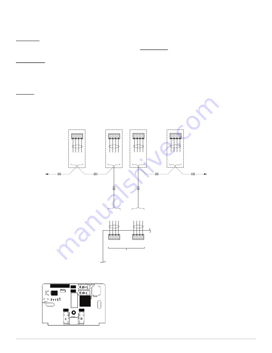
A04135
Fig. 2 – Typical Smart Sensor Wiring Diagram
A200273
Fig. 3 – Backplate
* ABCD Connections are in Parallel with each other.
Smart Sensors and Equipment may be connected in any combination.
For easier troubleshooting, the installer may elect to use one terminal block
for user interface and smart sensor connections, and the other for equipment connections.
NOTE:
DAMPER CONTROL MODULE
ZONES 1-4
A B C D
RED
GREEN
YELLOW
WHITE
SMAR
T
SENSOR(S)
T
O USER INTERF
ACE,
AND/OR
DAISY CHAIN
OPTION
TO OTHER
SMART SENSORS
IF AVAILABLE
TO EQUIPMENT OR
ACCESSORY CONNECTIONS
A
B
C
D
RED
COMMUNICATION
BUS
*
GREEN
YELLOW
WHITE
A
B
C
D
RED
GREEN
YELLOW
WHITE
A B C D
RED
GREEN
YELLOW
WHITE
A B C D
RED
GREEN
YELLOW
WHITE
A B C D
RED
GREEN
YELLOW
WHITE
T
O EQUIPMENT
, AND/OR
DAMPER CONTROL
MODULE
(ZONES 5-8)


