Installation Instructions
NOTE:
Read the entire instruction manual before starting the
installation.
Safety Considerations
Improper installation, adjustment, alteration, service, maintenance, or
use can cause explosion, fire, electrical shock, or other conditions which
may cause death, personal injury or property damage. Consult a
qualified installer, service agency or your distributor or branch for
information or assistance. The qualified installer or agency must use
factory-authorized kits or accessories when modifying this product.
Refer to the individual instructions packaged with the kits or accessories
when installing.
Follow all safety codes. Wear safety glasses, protective clothing, and
work gloves. Have a fire extinguisher available. Read these instructions
thoroughly and follow all warnings and cautions included in literature
and attached to the unit. Consult local building codes and the current
edition of the National Electrical Code (NEC) NFPA 70. In Canada,
refer to the current editions of the Canadian Electrical Code CSA C22.1.
Recognize safety information. When you see this symbol on the unit
and in instructions or manuals, be alert to the potential for personal
injury. Understand the signal words DANGER, WARNING, and
CAUTION. These words are used with the safety-alert symbol.
DANGER identifies the most serious hazards, which will result in severe
personal injury or death. WARNING signifies hazards, which could
result in personal injury or death. CAUTION is used to identify unsafe
practices, which may result in minor personal injury or product and
property damage. NOTE is used to highlight suggestions which will
result in enhanced installation, reliability, or operation.
Introductions
Smart Sensors are optional replacements for Remote Room Sensors used
with communicating Zoning systems (see equipment Product Data Sheet
for compatibility with this Smart Sensor). It provides a temperature
display on a touch screen to adjust the desired temperature within the
zone. It also displays outdoor temperature and indoor humidity. When
used with a Communicating System Control - FAN, HOLD and HOLD
UNTIL features are available.
Installation Considerations
Any zone may use a Smart Sensor. The Smart Sensor can be “home run”
wired directly to the Damper Control Module, or “daisy chained” from
the wall control or another Smart Sensor via 4-wire ABCD
communication bus. Ordinary thermostat wire is recommended;
however, solid conductor, stranded, or shielded wire may be used. Use
22 AWG or larger for normal wiring applications. Continuous wire
lengths over 100 ft. should use 20 AWG or larger. Plan the connection of
each Smart Sensor to provide easiest wiring route.
NOTE:
Whenever possible, it is suggested to always “home run” wires
back to the Damper Control Module for convenience of troubleshooting.
Using a “pig-tailed” connection, or a field supplied terminal block may
be helpful in achieving proper wire termination at the Damper Control
Module.
A Smart Sensor may now be used to control Zone 1. In addition, a
Remote Room Sensor may also be used in the same zone. If a Remote
Room Sensor is applied in the same zone, the Remote Room Sensor has
temperature priority over the Smart Sensor.
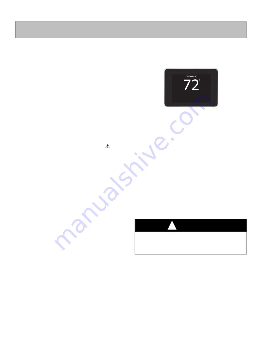
A200265
Fig. 1 – Smart Sensor SYSTXZNSMS01
Installation
Step 1 – Select Smart Sensor Location
Sensor should be mounted:
• Approximately 5 ft. (1.5m) from floor.
• Close to center of zone, preferably on inside partitioning wall.
• On section of wall without pipes or ductwork.
• Where wiring can be routed to it within wall. Avoid running directly
next to other AC power.
Sensor should NOT be mounted:
• Close to a window, on outside wall, or next to a door leading to the
outside.
• Exposed to direct light and heat from a lamp, sun, fireplace, or other
temperature radiating object which may cause a false reading.
• Close to or in direct airflow from supply registers and return-air
grilles.
• In areas with poor air circulation, such as behind a door or in an
alcove.
• Do not run wires next to AC power lines.
Step 2 – Install Smart Sensor
1. Turn OFF all power to unit.
2. If an existing thermostat or sensor is being replaced:
a. Remove existing device from wall.
b. Disconnect wires from existing device, 1 at a time. Be careful
not to allow wires to fall back into wall.
c. Discard or recycle old device.
d. If 4 wires exist in wall, they may be used. If not, plan and route
wiring to connect with either the Damper Control Module, or
User Interface. Multiple Smart Sensors may be daisy chained
together, but somewhere chain must connect to either Damper
SYSTXZNSMS01
Smart Sensor for Zoning
WARNING
!
ELECTRICAL SHOCK HAZARD
Failure to follow this warning could result in personal injury or death.
Before installing sensor, turn off all power to unit. There may be more
than 1 power disconnect.