background image

11

RISQUE D’EXPLOSION ET D’INCENDIE

Le fait de ne pas suivre cet avertissement pourrait entraîner des

dommages corporels et / ou la mort.
Ne jamais examiner pour les fuites de gaz avec une flamme

vive. Utilisez plutôt un savon fait specifiquement pour la

détection des fuites de gaz pour verifier tous les connections.

Un incendie ou une explosion peut entrainer des dommages

matériels, des blessures ou la mort.

!

AVERTISSEMENT

1. Be sure main gas and electric supplies to furnace are off.
2. Remove 1/8-in. NPT pipe plug from manifold pressure tap

on downstream side of gas valve.

3. Attach manometer to manifold pressure tap on gas valve.

(see Fig. 13.)

4. Turn gas supply manual shutoff valve to ON position.
5. Turn furnace gas valve switch to ON position.
6. Check all threaded pipe connections for gas leaks.
7. Turn on furnace power supply.
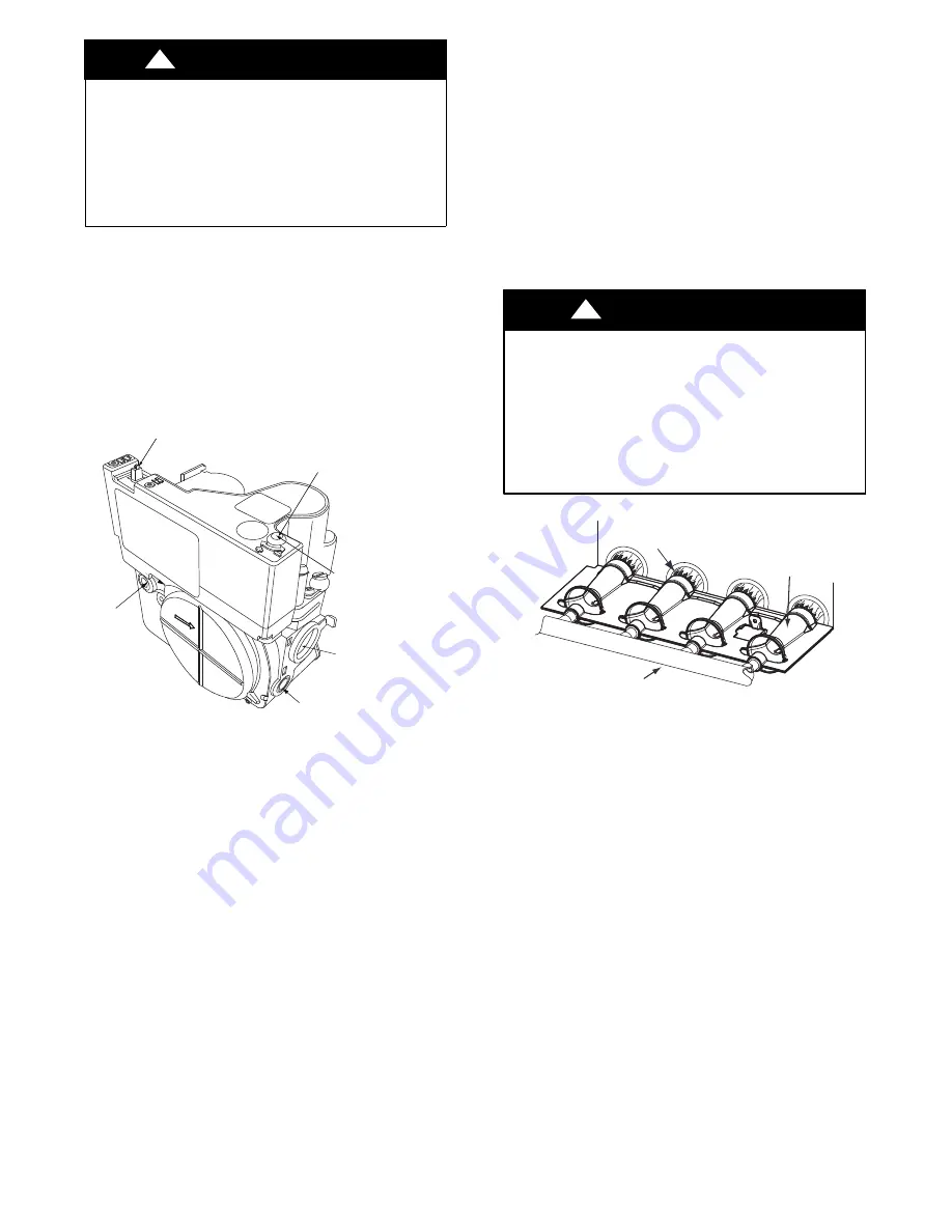
ON/OFF Switch

1/2” NPT Outlet

Manifold
Pressure Tap

 Inlet
Pressure Tap

Min/Max Heat Adust
(Under Cap)

GAS FL

OW

MODULATING

Turn screw 1 click per
second to adjust rate. 
Clockwise to increase
rate, counter clockwise
to decrease rate.

A11513

Fig. 13 -- Gas Valve

GAS INPUT RATE INFORMATION

See furnace rating plate on blower door for input rate. The input

rate for natural gas is determined by manifold pressure and orifice
size.
The gas valve must be set for Maximum Heat first and then set
for Minimum Heat on Modulating furnaces.
Determine natural gas orifice size and manifold pressures for

correct input at installed altitude by using Table 3 (for 20,000
Btuh/Max--Heat/8000 Btuh Min--Heat per Burner) or Table 4

(For 20,200 Btuh Max Heat/8,000 Btuh Min--Heat per Burner).

1. Obtain yearly heat--value average (at installed altitude) for

local gas supply.

2. Obtain yearly specific--gravity average for local gas sup-

ply.

3. Find installation altitude in Table 3 or Table 4, depending

on furnace gas input rate.

NOTE

: For Canada altitudes of 2000 to 4500 ft. (610 to 1372

M), use U.S.A. Altitudes of 2001 to 3000 ft. (610 to 914 M) in
Table 3 or Table 4, depending on furnace gas input rate.

4. Find closest natural gas heat value and specific gravity in

Table 3 or Table 4, depending on furnace gas input rate.

5. Follow heat--value line and specific--gravity line to point

of intersection to find orifice size and maximum and min-

imum manifold pressure settings.

Furnace gas input rate on rating plate is for installations at

altitudes up to 2000 ft. (610 M).
In the U.S.A., the input rating for altitudes above 2000 ft. (610M)

must be reduced by 2 percent for each 1000 ft. (305 M) above sea
level.
In Canada, the input rating must be derated by 5 percent for
altitudes of 2000 ft. (610 M) to 4500 ft. (1372 M) above sea

level.
The Conversion Kit Rating Plate accounts for high altitude
derate.

SET GAS INPUT RATE

UNIT DAMAGE HAZARD

Failure to follow this caution may result in gas valve

damage.
DO NOT force the rotary adjustment switch on the

modulating gas valve. DO NOT turn the rotary adjustment

switch faster than one click per second when adjusting

manifold pressure. Gas valve will be damaged if excessive

force is used on the rotary switch.

CAUTION

!

Burner Flame

Burner

Manifold

A11461

Fig. 14 -- Burner Flame

For proper operation and long term reliability, the manifold

pressure must be adjusted as specified on the conversion kit rating
plate.
The modulating furnace manifold pressure is set at two points.
The first point is Maximum Heat. The second point is Minimum

Heat. DO NOT adjust Intermediate Heat manifold pressure.
Intermediate Heat manifold pressure can be checked as part of the

temperature rise, but is not adjustable. Always adjust Maximum

Heat first, then Minimum Heat.

NOTE

: Use care when performing adjustments. Gas valve

adjustment is performed by turning a rotary adjustment switch
inside the gas valve with a small straight blade screwdriver.
Excessive force can break or bend the rotary adjustment switch
making it non--adjustable.
To adjust manifold pressure to obtain input rate for Maximum

Heat:

1. Make sure the gas supply is turned off to the furnace and

at the electric switch on the gas valve.

2. Remove the 1/8 inch NPT plug from the outlet pressure

tap on the gas valve.

3. Connect a manometer to the outlet pressure tap on gas

valve.

4. Turn on furnace power supply.
5. Turn gas supply manual shutoff valve to ON position.

Summary of Contents for KGBPN4401VSP

Page 1: ... basic maintenance functions such as cleaning and replacing air filters Trained service personnel must perform all other operations When working on heating equipment observe precautions in the literature on tags and on labels attached to or shipped with the unit and other safety precautions that may apply Follow all safety codes In the United States follow all safety codes including the current ed...

Page 2: ...5 ORIFICE 45 1 340071 701 LABEL SHEET Includes 1 340071 201 CONVERSION RATING PLATE 1 340071 202 GAS CONTROL CONVERSION LABEL 1 340071 203 GAS CONTROL ADJUSTMENT LABEL 1 340071 204 CONVERSION RATING PLATE 1 340071 205 CONVERSION RESPONSIBILITY LABEL 1 340071 702 LABEL SHEET Includes 1 340071 206 CONVERSION RATING PLATE 1 340071 209 CONVERSION RATING PLATE Kit Contents Continued 1 340071 703 LABEL ...

Page 3: ...CE SELECTION DERATE UNIT DAMAGE HAZARD Failure to follow this caution may result in unit damage DO NOT re drill burner orifices Improper drilling may result in burrs out of round holes etc Obtain new orifices if orifice size must be changed See Fig 4 CAUTION BURNER ORIFICE BURNER ORIFICE A96249 Fig 4 Burner Orifice Determine natural gas orifice size and manifold pressures for correct input at inst...

Page 4: ...3 3 6 0 55 43 3 7 0 60 875 44 3 6 0 60 44 3 7 0 60 43 3 4 0 55 43 3 5 0 55 4000 900 44 3 4 0 55 44 3 5 0 55 44 3 7 0 60 44 3 8 0 60 1219 925 44 3 2 0 50 44 3 4 0 55 44 3 5 0 55 44 3 6 0 55 950 45 3 7 0 60 44 3 2 0 50 44 3 3 0 55 44 3 4 0 55 750 42 3 3 0 50 42 3 4 0 55 42 3 5 0 55 42 3 6 0 55 4001 775 43 3 7 0 60 43 3 8 0 60 42 3 3 0 50 42 3 4 0 55 1220 800 43 3 5 0 55 43 3 6 0 60 43 3 7 0 60 43 3 ...

Page 5: ...5 8000 775 44 3 3 0 55 44 3 4 0 55 44 3 5 0 55 44 3 7 0 60 2438 800 45 3 8 0 60 44 3 2 0 50 44 3 3 0 55 44 3 4 0 55 825 46 3 7 0 60 46 3 8 0 60 45 3 8 0 60 44 3 2 0 50 625 42 3 4 0 55 42 3 5 0 55 42 3 6 0 55 42 3 7 0 60 8001 650 43 3 8 0 60 42 3 2 0 50 42 3 3 0 55 42 3 4 0 55 2439 675 43 3 5 0 55 43 3 6 0 60 43 3 7 0 60 42 3 2 0 50 700 44 3 7 0 60 43 3 4 0 55 43 3 5 0 55 43 3 6 0 55 725 44 3 5 0 5...

Page 6: ... 5 0 55 43 3 6 0 55 43 3 8 0 60 875 44 3 7 0 60 44 3 8 0 60 43 3 4 0 55 43 3 6 0 55 4000 900 44 3 5 0 55 44 3 6 0 55 44 3 7 0 60 43 3 4 0 55 1219 925 44 3 3 0 50 44 3 4 0 55 44 3 5 0 55 44 3 6 0 55 950 45 3 8 0 60 44 3 2 0 50 44 3 4 0 55 44 3 5 0 55 750 42 3 3 0 50 42 3 4 0 55 42 3 6 0 55 42 3 7 0 55 4001 775 43 3 8 0 60 42 3 2 0 50 42 3 3 0 50 42 3 4 0 55 1220 800 43 3 6 0 55 43 3 7 0 60 43 3 8 0...

Page 7: ...3 3 5 0 55 43 3 6 0 55 43 3 8 0 60 42 3 2 0 50 675 44 3 8 0 60 43 3 4 0 55 43 3 5 0 55 43 3 6 0 55 10000 700 44 3 5 0 55 44 3 6 0 55 44 3 7 0 60 44 3 8 0 60 3048 725 44 3 3 0 50 44 3 4 0 55 44 3 5 0 55 44 3 6 0 55 Orifice numbers shown in BOLD are factory installed U S A Only to U S A Only to U S A Only to A11621B Furnace gas input rate on furnace rating plate is for installations at altitudes up ...

Page 8: ...pane Jumper A11502 Fig 9 Removing Propane Jumper NOTE The Propane jumper for the modulating gas valve is very small Needle nose pliers are required to remove the jumper from the gas valve 1 Locate the round LP GAS sticker on the top of the gas valve 2 Peel the sticker off and discard 3 Note the small square opening in the top of the gas valve 4 Remove the small black plastic Propane jumper from th...

Page 9: ... Tee and brass nipple from the gas valve inlet pressure tap See Fig 11 NOTE Use pipe dope approved for use with Propane gas 2 Apply pipe dope sparingly to the 1 8 in NPT pipe plug provided in kit and install in the 1 8 in tapped inlet pressure tap opening in the gas valve DO NOT over tighten Check for gas leaks after gas supply has been turned on INSTALL MANIFOLD 1 Align the orifices in the manifo...

Page 10: ... Turn Setup Switch SW1 2 on furnace control ON see Fig 12 6 Jumper R W W1 and R W2 thermostat connections on control Model Plug Setup Switches SW1 1 thru 8 SW2 A C Air Flow Setup Switches AC 1 through AC 3 OAT PL9 A B C D PL4 HUM PL7 W2 Y1 DHUM SW4 SW2 SW3 Communication Connection 24 VAC HUM Output 0 5 AMP MAX SW3 Continuous Fan CF airflow setup switches CF 1 through CF 3 Outside Air Thermistor SW...

Page 11: ...ral gas heat value and specific gravity in Table 3 or Table 4 depending on furnace gas input rate 5 Follow heat value line and specific gravity line to point of intersection to find orifice size and maximum and min imum manifold pressure settings Furnace gas input rate on rating plate is for installations at altitudes up to 2000 ft 610 M In the U S A the input rating for altitudes above 2000 ft 61...

Page 12: ...t with straight run ducts 2 When thermometer readings stabilize subtract return air temperature from supply air temperature to determine air temperature rise 3 Allow the furnace to run for at least 10 minutes before checking Temperature Rise If the temperature rise is too high or too low in Minimum Heat 1 Remove jumpers from R and W W1 2 Wait until the blower off delay is completed 3 Turn 115 VAC ...

Page 13: ...13 A13203 Fig 15 Conversion Responsibility Label A13201 Fig 16 Conversion Kit Rating Plate A13207 Fig 17 Gas Control Conversion Label ...

Page 14: ...vous de bien suivre les instructions dans cette notice pour réduire au minimum le risque d incendie d explosion ou la production de monoxyde de carbone pouvant causer des dommages matériels de blessure ou la mort Le service d entretien qualifié est responsable de l installation de cette trousse L installation n est pas adéquate ni complète tant que le bon fonctionnement de l appereil converti n a ...

Page 15: ...reen Yellow ground wire here Manifold Gas Valve Gas valve must be installed on manifold with minimum engagement of 6 threads Cross threading is not acceptable Indicated surfaces to be 90 or 2 C L Gas valve is parallel to manifold within or 3 A11407 Fig 19 2 Stage Gas Valve FLAME SENSOR BELOW BURNER FLAME ROLLOUT SWITCH BRACKET IGNITER IGNITER BURNER SUPT ASSY BURNER ASSY A11403 Fig 20 Burner Assem...

Page 16: ...75 44 3 6 1 5 44 3 7 1 6 43 3 4 1 4 43 3 5 1 5 4000 900 44 3 4 1 4 44 3 5 1 5 44 3 7 1 5 44 3 8 1 6 1219 925 44 3 2 1 4 44 3 4 1 4 44 3 5 1 5 44 3 6 1 5 950 45 3 7 1 6 44 3 2 1 3 44 3 3 1 4 44 3 4 1 4 750 42 3 3 1 4 42 3 4 1 4 42 3 5 1 5 42 3 6 1 5 4001 775 43 3 7 1 6 43 3 8 1 6 42 3 3 1 4 42 3 4 1 4 1220 800 43 3 5 1 5 43 3 6 1 5 43 3 7 1 6 43 3 8 1 6 825 44 3 8 1 6 43 3 4 1 4 43 3 5 1 5 43 3 6 1...

Page 17: ...6 44 3 8 1 6 43 3 4 1 4 43 3 5 1 5 10000 700 44 3 4 1 4 44 3 5 1 5 44 3 7 1 5 44 3 8 1 6 3048 725 44 3 2 1 3 44 3 3 1 4 44 3 4 1 4 44 3 5 1 5 Orifice numbers shown in BOLD are factory installed to to to U S A Only U S A Only U S A Only A11252B Furnace gas input rate on furnace rating plate is for installations at altitudes up to 2000 ft 610 M In the U S A the input rating for altitudes above 2000 ...

Page 18: ... and install a lockout tag There may be more than one disconnect switch Lock out and tag switch with a suitable warning label Verify proper operation after servicing WARNING 1 Refer to Fig 25 2 Be sure gas and electrical supplies to furnace are off 3 Remove caps that conceal adjustment screws for high heat and low heat stage gas valve regulators See Fig 25 4 Remove the high heat and low heat regul...

Page 19: ...nipple from the gas valve inlet pressure tap See Fig 27 NOTE Use pipe dope approved for use with Propane gas DO NOT use Teflon tape 2 Apply pipe dope sparingly to the 1 8 in NPT pipe plug provided in kit and install in the 1 8 in tapped inlet pressure tap opening in the gas valve DO NOT over tighten Check for gas leaks after gas supply has been turned on Brass Street Brass Nipple For larger casing...

Page 20: ...this warning could result in personal injury and or death NEVER test for gas leaks with an open flame Use a commercially available soap solution made specifically for the detection of leaks to check all connections A fire or explosion may result causing property damage personal injury or loss of life WARNING RISQUE D EXPLOSION ET D INCENDIE Le fait de ne pas suivre cet avertissement pourrait entra...

Page 21: ...t rate NOTE When correct input is obtained main burner flame should be clear blue almost transparent see Fig 29 14 Jumper R W W1 and W2 on control center thermostat connections This keeps furnace locked in high heat oper ation 15 Adjust high heat manifold pressure for natural gas 16 Turn high heat adjusting screw counterclockwise out to decrease input rate or clockwise in to increase input rate 17...

Page 22: ...22 A13203 Fig 30 Conversion Responsibility Label A13204 Fig 31 Conversion Kit Rating Plate A13207 Fig 32 Gas Control Conversion Label ...

Page 23: ...xplosion ou la production de monoxyde de carbone pouvant causer des dommages matériels de blessure ou la mort Le service d entretien qualifié est responsable de l installation de cette trousse L installation n est pas adéquate ni complète tant que le bon fonctionnement de l appereil converti n a pas été vérfié selon les instructions du fabricant fornies avec la trousse AVERTISSEMENT FIRE EXPLOSION...

Page 24: ...manifold pressures for correct input at installed altitude by using Table 7 or 8 NOTE All models in all positions except Low NOx models in downflow and horizontal positions use Table 7 22 000 Btuh per burner Low NOx models in downflow or horizontal positions must use Table 8 21 000 Btuh per burner See input listed on rating plate 1 Obtain yearly heat value average at installed altitude for local g...

Page 25: ...1 5 43 3 5 1 5 43 3 6 1 6 925 44 3 5 1 5 43 3 2 1 4 43 3 3 1 4 43 3 4 1 5 950 44 3 4 1 5 44 3 5 1 5 44 3 6 1 6 43 3 2 1 4 975 44 3 2 1 4 44 3 3 1 4 44 3 4 1 5 44 3 5 1 5 1000 45 3 7 1 6 45 3 8 1 7 44 3 2 1 4 44 3 4 1 5 ALTITUDE RANGE FT M AVG GAS HEAT VALUE BTUH CU FT SPECIFIC GRAVITY OF NATURAL GAS 0 58 0 60 0 62 0 64 Orifice No Manifold Pressure High Low Orifice No Manifold Pressure High Low Ori...

Page 26: ... 1 6 850 47 3 5 1 5 47 3 6 1 6 47 3 8 1 6 46 3 4 1 5 ALTITUDE RANGE AVG GAS HEAT VALUE AT ALTITUDE BTUH CU FT SPECIFIC GRAVITY OF NATURAL GAS 0 58 0 60 0 62 0 64 Orifice No Manifold Pressure High Low Orifice No Manifold Pressure High Low Orifice No Manifold Pressure High Low Orifice No Manifold Pressure High Low USA 7001 to 8000 2134 to 2438 650 44 3 6 1 6 43 3 2 1 4 43 3 4 1 5 43 3 5 1 5 675 44 3...

Page 27: ...3 4 1 6 44 3 5 1 7 43 3 2 1 5 43 3 3 1 6 925 44 3 2 1 5 44 3 3 1 6 44 3 5 1 6 44 3 6 1 7 950 45 3 7 1 8 45 3 8 1 8 44 3 3 1 6 44 3 4 1 6 975 46 3 7 1 8 46 3 8 1 8 45 3 8 1 8 44 3 2 1 5 1000 46 3 5 1 7 46 3 6 1 7 46 3 8 1 8 45 3 7 1 8 ALTITUDE RANGE FT M AVG GAS HEAT VALUE BTUH CU FT SPECIFIC GRAVITY OF NATURAL GAS 0 58 0 60 0 62 0 64 Orifice No Manifold Pressure High Low Orifice No Manifold Pressu...

Page 28: ...8 1 8 850 48 3 7 1 7 48 3 8 1 8 47 3 4 1 6 47 3 5 1 7 ALTITUDE RANGE FT M AVG GAS HEAT VALUE AT ALTITUDE BTUH CU FT SPECIFIC GRAVITY OF NATURAL GAS 0 58 0 60 0 62 0 64 Orifice No Manifold Pressure High Low Orifice No Manifold Pressure High Low Orifice No Manifold Pressure High Low Orifice No Manifold Pressure High Low USA 7001 to 8000 2134 to 2438 650 44 3 3 1 6 44 3 4 1 6 44 3 5 1 7 43 3 2 1 5 67...

Page 29: ...sembly 3 Insert one piece burner in slot on sides of burner box and slide burner back in place 4 Reattach HSI wires to HSI 5 Verify igniter to burner alignment 6 For Silicon Nitride igniters see Fig 38 and 39 7 For Silicon Carbide igniters see Fig 40 8 Re attach Flame Sensor wire to Flame Sensor 1 7 8 47 6 mm A05026 Fig 39 Igniter Position Top View A93347 Fig 40 Silicon Carbide Igniters CONVERT GA...

Page 30: ...s at this time For E valves see Fig 42 1 Be sure gas and electrical supplies to furnace are off 2 Remove caps that conceal adjustment screws for high and low heat stage gas valve regulators See Fig 42 3 Turn low heat stage adjusting screw 3 32 in 2 mm hex Allen screw counter clockwise outwards 1 full turn This will decrease the manifold pressure closer to the nat ural low heat set point 4 Turn hig...

Page 31: ...ow wire and ground terminal to one of the manifold mounting screws 4 Install the remaining manifold mounting screws 5 Connect the wires to both rollout switches 6 Connect the wires to the flame sensor and hot surface ig niter 7 Connect the connector harness to gas valve 8 Rewire unit low pressure switch LPS as follows a Trace one of the orange wires previously disconnected from the LGPS back to th...

Page 32: ... servicing system main electrical disconnect switch must be in the OFF position and install a lockout tag There may be more than one disconnect switch Lock out and tag switch with a suitable warning label Verify proper operation after servicing WARNING 1 Be sure main gas and electric supplies to furnace are off 2 Remove 1 8 in NPT pipe plug from manifold pressure tap on downstream side of gas valv...

Page 33: ... high heat ad justment to terminate call for heat 19 Turn setup switch SW1 2 on furnace control to OFF posi tion 20 Turn furnace gas valve switch to OFF position 21 Turn off furnace power supply 22 Remove manometer and re install manifold pressure tap plug 23 Turn furnace gas valve switch to ON position 24 Turn on furnace power supply 25 Set room thermostat to call for heat 26 Check pressure tap p...

Page 34: ...208 Fig 49 Gas Control Adjustment Label Copyright 2013 CAC BDP D 7310 W Morris St D Indianapolis IN 46231 Manufacturer reserves the right to change at any time specifications and designs without notice and without obligations Catalog No AG KGBPNVSP 01 Replaces AG KGAPNVSP 04 Edition Date 08 13 ...

Reviews: