background image

A02204a

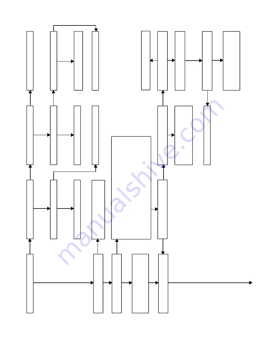
Is LED status light on?

Is LED status light b

linking r

apidly without a

pause?

Is LED status light b

linking ON/OFF slo

wly

with a combination of shor

t and long flashes?

Deter

mine status code

.  

The status code is a

2 digit n

umber with the first digit deter

mined

b

y

 the n

umber of shor

t flashes and the second

digit b

y

 the n

umber of long flashes?

Go to section belo

w f

or the status code that

w

as flashed.

Is there 115V at L1 and L2?

Is there 24V at SEC-1 and SEC-2?

Replace fur

nace control.

Chec

k f

or correct line v

oltage polar

ity

.  If units

are twinned, chec

k f

or proper lo

w-v

oltage

(24V) tr

ansf

or

mer phasing.

T

o

 recall status code br

iefly remo

v

e

 and reconnect one RED wire from the Limit

Switch or Flame Rollout s

witch to displa

y stored status code

.  On RED LED

control do not remo

v

e

 po

w

er or b

lo

w

er access panel bef

ore initiating status

code recall.

  Y

ou can also recall the pre

vious status code b

y

 momentar

ily shor

ting

the 

TEST/TWIN ter

minal to Com24V ter

minal until the LED goes out.

  LED will

flash the pre

vious status code or status code #11 (1 shor

t and 1 long flash) if

there w

as no pre

vious code

.  After the control repeats the code 4 times

, the

control will go through a br

ief component test sequence

.  

The inducer will star

t

and r

un f

or the entire component test.


The HSI, b

lo

w

er motor F

AN speed

(AMBER LED boards only) HEA

T speed, and COOL speed will r

un f

or 10 

 15

seconds each.

  Gas v

alv

e and humidifier will not be tur

ned on.

W

as there a pre

vious status code

other than #11?

Is door s

witch closed?

Is there 115V going to s

witch?

Replace door s

witch.

Replace tr

ansf

or

mer

.

Does the control respond to 

W

, Y1 (if present),

Y/Y2, and G (24V)  ther

mostat signals?

Run system through a heating or cooling cycle

to chec

k oper

ation.

  Status codes are er

ased

after 72 hours

.  On RED LED boards stored

status codes can also be er

ased whene

v

e

r

(115V or 24V) is interr

upted.

Replace fur

nace control.

Close door s

witch and go bac

k to ST

AR

T

.

Is circuit break

er closed?

Chec

k f

or contin

uity in wire from circuit break

er

to fur

nace

.

Close circuit break

er and go bac

k to ST

AR

T

.

Chec

k room ther

mostat or

interconnecting cab

le

.

Is 24V present at 

W

Y1 (if present), 

Y/Y2 or

G ther

mostat ter

minals on the fur

nace control?

Disconnect all the ther

mostat wires from the

fur

nace control.

Does the prob

lem repeat when using

a jumper wire?

The ther

mostat is not compatib

le with the

fur

nace control.

  Either install a ballast resistor

,

connect the Com24V ther

mostat ter

minal to

the ther

mostat, or replace the ther

mostat.

NO

YES

YES

NO

NO

YES

YES

YES

YES

NO

YES

YES

NO

YES

NO

YES

NO

NO

NO

YES

NO

YES

NO

ST

AR

T

TR

OUBLESHOO

TING GUIDE

NO

14

Summary of Contents for GAS FURNACE 58MXA

Page 1: ...aning com pounds plastic or plastic containers gasoline kerosene cigarette lighter fluid dry cleaning fluids or other volatile fluids 3 Paint thinners and other painting compounds paper bags or other paper products Failure to follow this warning can cause corrosion of the heat exchanger fire personal injury or death NOTE Read the entire instruction manual before starting the installation This symb...

Page 2: ...talled in any of the 4 positions shown in Fig 2 you may need to revise your orientation to component location accordingly ELECTROSTATIC DISCHARGE ESD PRECAUTIONS Electrostatic discharge can affect electronic components Take precautions during furnace installation and servicing to protect the furnace electronic control Precautions will pre vent electrostatic discharges from personnel and hand tools...

Page 3: ...et adjacent to furnace 1 Turn off electrical supply to furnace 2 Remove filter cabinet door 3 Slide filter out of cabinet 4 If equipped with permanent washable filter clean filter by spraying cold tap water through filter in opposite direction of airflow Rinse filter and let dry Oiling or coating of the filter is not recommended 5 If equipped with factory specified disposable media filter replace ...

Page 4: ...stall blower assembly in furnace 11 Reinstall control box transformer and door switch assembly on blower shelf 12 Reinstall condensate trap and tubing if previously removed a Reinstall condensate trap in hole in blower shelf b Connect condensate trap drain tubes See Fig 8 or tubing diagram on main furnace door for proper tube location NOTE Ensure tubes are not kinked or pinched as this will affect...

Page 5: ...exchangers get an accumulation of light dirt or dust on the inside they may be cleaned by the following procedure NOTE If the heat exchangers get a heavy accumulation of soot and carbon both the primary and secondary heat exchangers should be replaced rather than trying to clean them thoroughly due to their intricate design A build up of soot and carbon indicates that a problem exists which needs ...

Page 6: ...ndary heat exchangers CANNOT be serviced or inspected A small number of bottom outlet openings can be inspected by removing the inducer assembly See Flushing Collector Box and Drainage System section for details on removing inducer assembly Step 5 Flushing Collector Box and Drainage System 1 Turn off gas and electrical supplies to furnace 2 Remove main furnace door 3 Disconnect inducer motor and p...

Page 7: ...UE PLUGGED END COLLECTOR BOXDRAIN TUBE BLUE WHITE STRIPED COLLECTOR BOX TUBE GREEN COLLECTOR BOX TUBE PINK COLLECTOR BOX EXTENSIONTUBE CONDENSATE TRAP INDUCER HOUSINGDRAIN TUBE VIOLET COLLECTOR BOX EXTENSION TUBE COLLECTOR BOXTUBE PINK COLLECTOR BOX DRAIN TUBE BLUE COLLECTOR BOX TUBE GREEN CONDENSATE TRAP INDUCER HOUSINGDRAIN TUBE VIOLET COLLECTOR BOX EXTENSION TUBE COLLECTOR BOXDRAIN TUBE BLUE WH...

Page 8: ...block out of bracket 6 To replace igniter igniter assembly reverse items 5a through 5d 7 Reconnect igniter wire connection 8 Turn on gas and electrical supplies to furnace 9 Verify igniter operation by initiating furnace control board self test feature or by cycling thermostat 10 Replace main furnace door Step 7 Electrical Controls and Wiring There may be more than 1 electrical supply to the unit ...

Page 9: ...d must be replaced use same type or equivalent wire W Y Y2 GND THERMOSTAT TERMINALS 1 2 3 Fig 12 Control Center A02142 BLW NUETRAL STATUS CODE LED SEC 2 SEC 1 EAC 2 L2 FUSE 3 AMP 0 5 AMP 24VAC HUM TEST TWIN Y1 DHUM G COM W W1 Y Y2 R 24V PLT 120 180 90 150 BLOWER OFF DELAY PLT 1 COOL HEAT SPARE 1 SPARE 2 FAN EAC 1 1 AMP 115VAC PR 1 L1 PL2 1 24 V THERMOSTAT TERMINALS 3 AMP FUSE LED OPERATION DIAGNOS...

Page 10: ... heat tape insulation If any damage or discolored insulation is evident replace heat tape 3 Check that heat tape power supply circuit is on Step 9 Winterizing Freezing condensate left in the furnace will damage the equipment If the furnace will be off for an extended period of time in a structure where the temperature will drop to 32 F or below winterize as follows 1 Turn off electrical supply to ...

Page 11: ...nger periods of time as the control will assume an overtemperature condition exists and will respond with blower operation This places the control in the status recall mode and displays the last code stored in memory Record the code After the last code is displayed the control will perform the component test and then return to normal standby mode COMPONENT TEST Blower access panel door switch open...

Page 12: ...UM 24VAC HUMIDIFIER CONNECTION 0 5 AMP MAX IDM INDUCED DRAFT MOTOR PSC IDR INDUCED DRAFT MOTOR RELAY SPST N O ILK BLOWER ACCESS PANEL INTERLOCK SWITCH SPST N O J1 BLOWER OFF DELAY JUMPER SELECTOR JB JUNCTION BOX LED LIGHT EMITTING DIODE FOR STATUS CODES AMBER LGPS LOW GAS PRESSURE SWITCH SPST N O LS LIMIT SWITCH AUTO RESET SPST N C OL AUTO RESET INTERNAL MOTOR OVERLOAD TEMPERATURE SWITCH N C PCB P...

Page 13: ...ing 31 PRESSURE SWITCH DID NOT CLOSE OR REOPENED If open longer than five minutes inducer shuts off for 15 minutes before retry Check for Excessive wind Proper vent sizing Defective inducer motor Low inducer voltage 115VAC Defective pressure switch Inadequate combustion air supply Restricted vent Disconnected or obstructed pressure tubing Low inlet gas pressure if LGPS used If it opens during blow...

Page 14: ...test sequence The inducer will start and run for the entire component test The HSI blower motor FAN speed AMBER LED boards only HEAT speed and COOL speed will run for 10 15 seconds each Gas valve and humidifier will not be turned on Was there a previous status code other than 11 Is door switch closed Is there 115V going to switch Replace door switch Replace transformer Does the control respond to ...

Page 15: ...stricted vent Proper vent sizing Excessive wind Blower motor on incorrect speed tap Input rate to furnace set too high 34 IGNITION PROVING FAILURE If flame is not sensed during the trial for ignition period the control will repeat the ignition sequence 3 more times before lockout 14 occurs If flame signal is lost during the blower on delay period blower will come on for the selected blower off del...

Page 16: ...31 58mxa9sm Manufacturer reserves the right to discontinue or change at any time specifications or designs without notice and without incurring obligations Book 1 4 Tab 6a 8a PC 101 Catalog No 535 80099 Printed in U S A Form 58MXA 9SM Pg 16 11 02 Replaces 58MXA 8SM ...

Reviews: