


43
Remote on-off control
Remote on-off control may be applied by hard-wired con-
nection (see Controls and Troubleshooting literature) or by
connection to a Carrier Comfort Network
®
(CCN) system.
Optional hydronic system selection
Select pump gpm from resulting chiller selection and total
pressure loss in the system plus the chiller internal pressure
loss.
NOTE: Maximum gpm (L/s), pressure and pump hp must
not exceed maximum on pump curve.
Pump flow can be reduced using factory-supplied balanc-
ing valve up to 10%. Beyond that, impeller trimming is rec-
ommended to reduce energy consumption. Contact your
Carrier representative for specific amount of trim required.
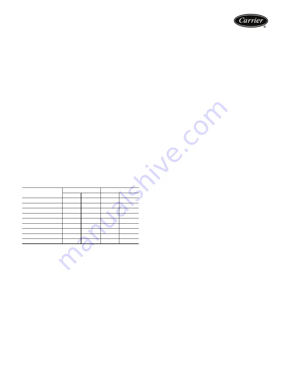
Expansion tank supplied will allow loop expansion due
to ambient fluctuations for loop volumes of up to the values
in the table below. If loop volume exceeds the maximum
loop volume, a larger expansion tank must be field
supplied.
The supplied expansion tanks have the following specifi-
cations: 30RA010-030 — 5.0 total gal., 2.4 gal. accep-
tance volume, 30RA035-055 — 10.0 total gal., 5.5 gal.
acceptance volume.
Maximum loop volume is based on typical system pres-
sure of 12 psig (83 kPa) and 30 psig (207 kPa) of mini-
mum and maximum pressures, and 100 F (37.8 C) mean
temperature.
MAXIMUM LOOP VOLUME
LEGEND
Parallel chillers with hydronic packages require that pump
inlets be equalized to prevent pump cavitation. Pump
expansion tanks must be removed and located together in
the common pump suction header. All materials needed
for expansion tank relocation are field supplied. Appropri-
ate measures must be taken for freeze protection.
Air separation
For proper system operation, it is essential that water
loops be installed with proper means to manage air in the
system. Free air in the system can cause noise, reduce ter-
minal output, stop flow, or even cause pump failure due to
pump cavitation. For closed systems, equipment should be
provided to eliminate all air from the system.
The amount of air that water can hold in solution depends
on the pressure and temperature of the water/air mixture.
Air is less soluble at higher temperatures and at lower pres-
sures. Therefore, separation can best be done at the point
of highest water temperature and lowest pressure. Typical-
ly, this point would be on the suction side of the pump as
the water is returning from the system or terminals. Gener-
ally speaking, this is the best place to install an air separa-
tor, if possible.
1. Install automatic air vents at all high points in the sys-
tem. (If the 30RA unit is located at the high point of
the system, a vent can be installed on the piping
entering the heat exchanger on the ¼-in. NPT female
port.)
2. Install an air separator in the water loop, at the place
where the water is at higher temperatures and lower
pressures — usually in the chilled water return piping.
On a primary-secondary system, the highest tempera-
ture water is normally in the secondary loop, close to
the decoupler. Preference should be given to that
point on the system. In-line or centrifugal air separa-
tors are readily available in the field.
It may not be possible to install air separators at the place
of lowest pressure and highest temperature. In such cases,
preference should be given to the points of highest
temperature. It is important that pipe be sized correctly so
that free air can be moved to the point of separation. Gen-
erally, a water velocity of at least 2 ft per second (0.6 m
per second) will keep free air entrained and prevent it from
forming air pockets.
Automatic vents should be installed at all physically elevat-
ed points in the system so that air can be eliminated during
system operation. Provision should also be made for man-
ual venting during the water loop fill. It is important that
the automatic vents be located in accessible locations for
maintenance purposes, and that they be located where
they can be prevented from freezing.
Minimum time to power chiller before
start-up
In order to ensure that the crankcase heaters are provided
sufficient time to raise the crankcase temperature to the
required operating point, power must be applied to the
chiller and the compressor circuit breakers must be on a
minimum of 24 hours prior to chiller start-up.
CONCENTRATION
30RA010-030
30RA035-055
GAL.
L
GAL.
L
PURE WATER
310
1173
725
2744
10% EG
180
681
425
1609
20% EG
175
662
410
1552
30% EG
155
587
370
1401
40% EG
150
568
350
1325
10% PG
175
662
410
1552
20% PG
150
568
350
1325
30% PG
128
485
300
1136
40% PG
118
447
275
1041
EG —
Ethlyene Glycol
PG —
Propylene Glycol