


42
Multiple chillers
Where chiller capacities greater than 55 tons (180 kW) are
required, or where standby capability is desired, chillers
may be installed in parallel. The flow must be balanced
according to the recommendations for each chiller.
Where applied in parallel with optional hydronic pack-
age, expansion tank must be disconnected and a single
expansion tank must be installed in the system.
Unit software is capable of controlling two units as a sin-
gle plant. Refer to Controls, Start-Up, Operation, Service,
and Troubleshooting guide for further details. Hydronic
pump package may not be applied in series applications.
Condenser coil protection (
Enviro-Shield
™)
Refer to the Environmental Corrosion Protection white
paper for more information.
Pre-coated aluminum-fin coils
have a durable epoxy-
phenolic coating applied to the fin prior to the fin stamping
process to provide protection in mildly corrosive coastal
environments. Pre-coated coils have an inert barrier
between the aluminum fin and copper tube. This barrier
electrically disconnects the dissimilar metals to minimize
the potential for galvanic corrosion. This economical
option provides substantial corrosion protection beyond
the standard uncoated coil construction.
Copper-fin coils
provide increased corrosion resistance
in moderate coastal environments where industrial air pol-
lution is not present. All-copper coils eliminate bimetallic
construction to eliminate the potential for galvanic corro-
sion. Application in industrial environments is not recom-
mended due to potential attack from sulfur, sulfur oxide,
nitrogen oxides, carbon and several other industrial air-
borne contaminants. In moderate seacoast environments,
copper-fin coils have extended life compared to standard
or pre-coated aluminum-fin coils.
E-coated aluminum-fin coils
have an extremely flexible
and durable epoxy coating uniformly applied to all coil
surfaces. Unlike brittle phenolic dip and bake coatings,
e-coat provides superior protection with unmatched flexi-
bility, edge coverage, metal adhesion, thermal perfor-
mance and most importantly, corrosion resistance.
E-coated coils provide this protection since all coil surfaces
are completely encapsulated from environmental contami-
nation. Specify e-coated aluminum-fin coils for industrial
environments with high levels of air pollution. This option
also provides better protection compared to standard or
pre-coated aluminum-fin coils in industrial environments.
E-coated copper-fin coils
have the same flexible and
durable epoxy coating as e-coated aluminum-fin coils.
However, this option combines the natural salt and envi-
ronmental resistance of all-copper construction with the
highest level of corrosion protection. Specify e-coated
copper-fin coils in the harshest combination of coastal and
industrial environments.
Electrical/utility interests
Energy management —
Use of energy management
practices can significantly reduce operating costs, espe-
cially during off-peak modes of operation. Demand limiting
and temperature reset are 2 techniques for accomplishing
efficient energy management. See Demand Limiting (also
called load shedding) section on this page for further
details.
Demand limiting (load shedding)
When a utility’s demand for electricity exceeds a certain
level, loads are shed to keep electricity demand below a
prescribed maximum level. Typically, this happens on hot
days when air conditioning is most needed. The energy
management module (EMM) can be added to accomplish
this reduction. Demand may be limited on unit by resetting
fluid temperature, or by unloading the chiller to a given
predetermined percentage of the load. Demand limit may
also be driven by an external 4 to 20 mA signal. These fea-
tures require a signal from an intelligent central control. Do
not cycle demand limiter for less than 10 minutes on and
5 minutes off. Duty cycling cycles electrical loads at regular
intervals regardless of need. This reduces the electrical
operating costs of building by “fooling” demand indicating
devices. Duty cycling of compressors or fans is not recom-
mended since motor winding and bearing life will suffer
from constant cycling.
Application data (cont)
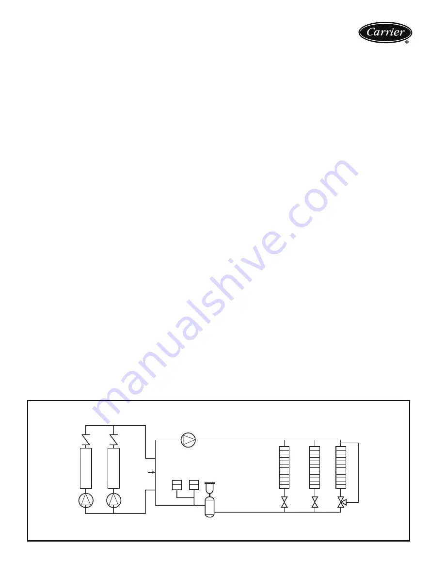
TYPICAL MULTIPLE CHILLER CONFIGURATION WITH AIR ELIMINATOR AND EXPANSION TANK LOCATION
Distri
b
ution Pump
Expansion
Tank(s)
Air Separator
with Vent
Decoupler
Chiller 1
Chiller 2
Zone 1
Zone 2
Zone 3