background image

4

1 - INTRODUCTION

Prior to the initial start-up of the 30RW/30RWA units, the 
people involved in the on-site installation, start-up, operation 
and maintenance of this unit should be thoroughly familiar 
with these instructions and the specific project data for the 
installation site.

The 30RW/30RWA liquid chillers are designed to provide a 
very high level of safety during installation, start-up, opera-
tion and maintenance. They will provide safe and reliable 
service when operated within their application range.

This manual provides the necessary information to fami-
liarize yourself with the control system before performing 
start-up procedures. The procedures in this manual are 
arranged in the sequence required for machine installation, 
start-up, operation and maintenance.

Be sure you understand and follow the procedures and 
safety precautions contained in the instructions supplied 
with the machine, as well as those listed in this guide.

To find out, if these products comply with European 
directives (machine safety, low voltage, electromagnetic 
compatibility, equipment under pressure etc.) check the 
declarations of conformity for these products.

1.1 - Installation safety considerations

After the unit has been received, when it is ready to be 
installed or reinstalled, and before it is started up, it must be 
inspected for damage. Check that the refrigerant circuit(s) 
is (are) intact, especially that no components or pipes have 
shifted (e.g. following a shock). If in doubt, carry out a leak 
tightness check and verify with the manufacturer that the 
circuit integrity has not been impaired. If damage is detected 
upon receipt, immediately file a claim with the shipping 
company.

Do not remove the skid or the packaging until the unit is 
in its final position. These units can be moved with a fork 
lift truck, as long as the forks are positioned in the right 
place and direction on the unit.

The units can also be lifted with slings, using only the 
designated lifting points marked on the unit.

These units are not designed to be lifted from above. Use 
slings with the correct capacity, and always follow the 
lifting instructions on the certified drawings supplied with 
the unit.
 
Safety is only guaranteed, if these instructions are carefully 
followed. If this is not the case, there is a risk of material 
deterioration and injuries to personnel. 

DO NOT COVER ANY PROTECTION DEVICES. 

This applies to fuse plugs and safety valves (if used) in the 
refrigerant or heat transfer medium circuits. Check if the 
original protection plugs are still present at the valve outlets. 
These plugs are generally made of plastic and should not be 
used. If they are still present, please remove them. Install 
devices at the valve outlets or drain piping that prevent the 
penetration of foreign bodies (dust, building debris, etc.) and 
atmospheric agents (water can form rust or ice). These 
devices, as well as the drain piping, must not impair 
operation and not lead to a pressure drop that is higher 
than 10% of the control pressure.

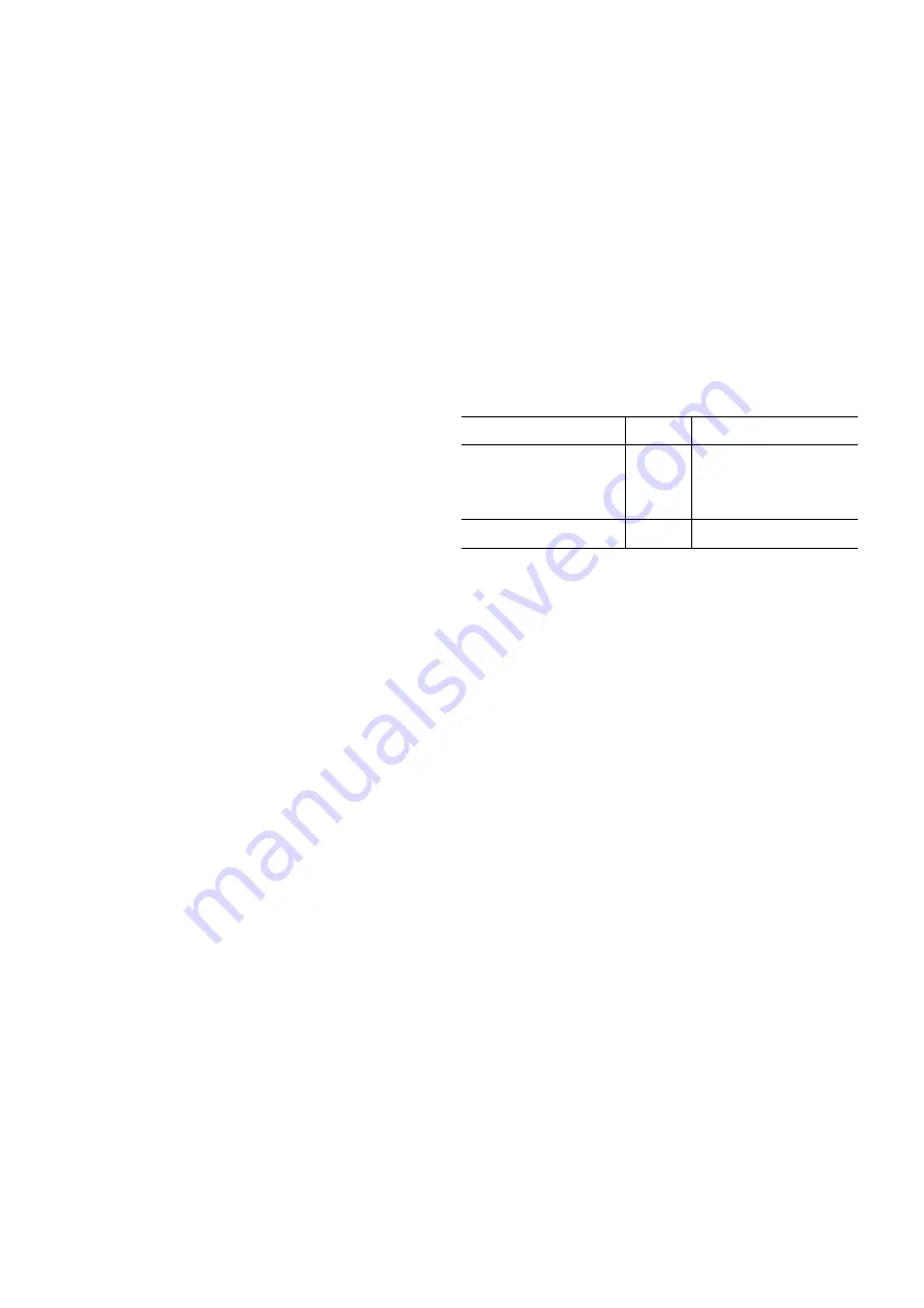
Classification and control
In accordance with the Pressure Equipment Directive and 
national usage monitoring regulations in the European 
Union the protection devices for these machines are 
classified as follows:

Safety 

accessory*

Damage limitation accessory** 

in case of an external fire

Refrigerant side

High-pressure switch

x

External relief valve***

x

Rupture disk

x

Fuse plug

x

Heat transfer fluid side

External relief valve****

x

x

*  Classified for protection in normal service situations.

**  Classified for protection in abnormal service situations.

***  The instantaneous over-pressure limited to 10% of the operating pressure 

does not apply to this abnormal service situation. The control pressure can be 

higher than the service pressure. In this case either the design temperature or 

the high-pressure switch ensures that the service pressure is not exceeded in 

normal service situations.

****  The classification of these safety valves must be made by the personnel that 

completes the whole hydronic installation.

Do not remove these valves and fuses, even if the fire risk 
is under control for a particular installation. There is no 
guarantee that the accessories are re-installed if the instal-
lation is changed or for transport with a gas charge.

All factory-installed safety valves are lead-sealed to 
prevent any calibration change. If the safety valves are 
installed on a reversing valve (change-over), this is 
equipped with a safety valve on each of the two outlets. 
Only one of the two safety valves is in operation, the other 
one is isolated. Never leave the reversing valve in the 
intermediate position, i.e. with both ways open (locate the 
control element in the stop position). If a safety stop is 
removed for checking or replacement please ensure that 
there is always an active safety stop on each of the reversing 
valves installed in the unit.

The external safety valves must always be connected to 
drain pipes for units installed in a closed room. Refer to 
the installation regulations, for example those of European 
standard EN 378 and EN 13136.

These pipes must be installed in a way that ensures that 
people and property are not exposed to refrigerant leaks. 
As the fluids can be diffused in the air, ensure that the 
outlet is far away from any building air intake, or that 
they are discharged in a quantity that is appropriate for a 
suitably absorbing environment.

Summary of Contents for Aquasnap 30RW

Page 1: ...30RW RWA Water Cooled Condenserless Liquid Chillers with Integrated Hydronic Modules Nominal cooling capacity 20 310 kW 50 Hz Installation operation and maintenance instructions...

Page 2: ...5 5 3 Operating range 30RWA 16 5 4 Minimum chilled water flow 16 5 5 Maximum chilled water flow 16 5 6 Variable flow evaporator 16 5 7 Evaporator flow rate 16 5 8 Condenser water flow rate l s 16 5 9...

Page 3: ...enser model used in the installation 31 12 6 Possible fan arrangements based on the air cooled condenser type used in the installation 32 13 START UP 34 13 1 Preliminary checks 34 13 2 Actual start up...

Page 4: ...erally made of plastic and should not be used If they are still present please remove them Install devices at the valve outlets or drain piping that prevent the penetration of foreign bodies dust buil...

Page 5: ...ituated on the liquid line before the filter drier box Any intervention on the refrigerant circuit including changing of drier blocks is only permitted after the complete removal of the refrigerant ch...

Page 6: ...ant on skin or splashing it into the eyes Use safety goggles and safety gloves Wash any spills from the skin with soap and water If liquid refrigerant enters the eyes immediately and abundantly flush...

Page 7: ...ersons 2 2 Moving and siting the unit 2 2 1 Moving See chapter 1 1 Installation safety considerations 2 2 2 Siting the unit Always refer to the chapter Dimensions and clearances to confirm that there...

Page 8: ...its B Evaporator C Refrigerant inlet outlet 30RW only 1 Clearances required for maintenance Power supply NOTE Non contractual drawings Refer to the certified dimensional drawings For the positioning o...

Page 9: ...let for 30RW units B Evaporator C Refrigerant inlet outlet 30RW only 1 Clearances required for maintenance Power supply NOTE Non contractual drawings Refer to the certified dimensional drawings For th...

Page 10: ...ts B Evaporator C Refrigerant inlet outlet 30RW only 1 Clearances required for maintenance Power supply NOTE Non contractual drawings Refer to the certified dimensional drawings For the positioning of...

Page 11: ...ed by frequency converter 48 3 r s Power input kW 2 5 2 5 2 5 2 5 2 5 2 5 2 5 2 5 2 5 5 0 5 0 5 0 5 0 5 0 5 0 6 7 6 7 6 7 6 7 Expansion tank volume condenser loop l 8 8 8 8 8 12 12 12 25 25 25 25 25 3...

Page 12: ...r and the pumps the control devices Field connections All connections to the system and the electrical installations must be in full accordance with all applicable local codes The Carrier 30RW and 30R...

Page 13: ...pumps 30RW 30RWA option 116C No Description 30RW 30RWA 060 070 080 090 110 120 135 150 160 185 210 245 275 300 1 Nominal efficiency at full load and nominal voltage 83 2 83 2 83 2 83 2 86 1 86 1 86 1...

Page 14: ...variable speed pump No Description 30RW 060 070 080 090 110 120 135 150 160 185 210 245 275 300 1 Nominal efficiency at full load and nominal voltage 83 2 83 2 83 2 83 2 86 1 86 1 86 1 87 6 87 6 87 6...

Page 15: ...low leaving water temperature and use of antifreeze is required 2 30RW units without hydronic module operating below 20 C entering condenser water temperature require the use of a three way valve cont...

Page 16: ...r units without hydronic module that have a fixed condenser flow rate Units with a hydronic module have a variable flow rate and no minimum fixed flow rate The minimum flow rate is optimised by unit c...

Page 17: ...er mixing of the liquid water or brine Refer to the examples below Bad Bad Good Good 5 10 Maximum water loop volume evaporator and condenser side Units with hydronic module incorporate an expansion ta...

Page 18: ...er flow rate l s Legend 1 30RW 020 2 30RW 025 030 3 30RW 040 4 30RW 045 5 30RW 060 6 30RW 070 7 30RW 080 8 30RW 090 9 30RW 110 10 30RW 120 11 30RW 135 12 30RW 150 13 30RW 160 185 14 30RW 210 245 15 30...

Page 19: ...at the main disconnect switch Before connecting electric power cables it is imperative to check the correct order of the 3 phases L1 L2 L3 Non certified drawings Refer to the certified dimensional dr...

Page 20: ...switch are designed for the number and type of wires listed in the table below The calculations are based on the maximum machine current see electrical data tables For the design the following standar...

Page 21: ...0 Ohm m are desirable A neutral environment favours maximum specific resistance values For electric conductivity values in the order of 20 60 mS m can be recommended 10 pH Ideal case pH neutral at 20...

Page 22: ...y Damage due to freezing is not covered by the warranty IMPORTANT Depending on the climatic conditions in your area you must Add ethylene glycol with an adequate concentration to protect the installat...

Page 23: ...Pressure gauge to measure the plate heat exchanger pressure drop to be isolated with valve No 5 if not used 7 Plate heat exchanger Legend Components of unit and hydronic module 1 Victaulic screen filt...

Page 24: ...The air cooled condenser must always be used with a subcooler normally with 8 K subcooling 8 2 General Refrigerant pipe sizing must be carried out taking account of the following constraints Oil retur...

Page 25: ...a saturated suction temperature of 4 C and 8 K subcooling Table 3 shows the correction factors to be applied to the values from Table 2 if the operating conditions are different from those previously...

Page 26: ...ing temperature C Outside pipe diameter inch 1 2 5 8 3 4 7 8 1 1 8 1 3 8 1 5 8 2 1 8 2 5 8 3 1 8 3 5 8 4 1 8 27 0 81 1 48 2 39 3 66 7 14 12 06 18 64 37 21 63 94 99 81 145 60 201 98 32 0 84 1 51 2 46 3...

Page 27: ...the forced start command refer to the controls manual and let the pump run for two con secutive hours to clean the hydronic circuit of the system presence of solid contaminants Read the plate heat ex...

Page 28: ...300 1 2 3 4 0 25 50 75 100 125 150 175 200 2 4 6 8 10 50 100 150 200 250 0 5 10 15 20 25 2 1 4 3 0 50 100 150 200 250 0 5 10 15 20 25 30 2 1 3 9 3 Available static system pressure evaporator side Sing...

Page 29: ...0 50 100 150 200 250 0 5 10 15 20 25 30 0 50 100 150 200 250 0 5 10 15 20 25 30 2 1 3 10 2 Available static system pressure condenser side Single pump Legend 1 30RW 020 2 30RW 025 030 3 30RW 040 4 30R...

Page 30: ...st efficiency with variation of the water flow rate and the number of fans required for any thermal load and outside temperature conditions The electronic board AUX1 integrated in the control box of t...

Page 31: ...This is the first fan to start in each circuit and the last fan to stop A fan configuration with fixed speed fans permits year round system operation down to 0 C outside temperature A fan configurati...

Page 32: ...B from fan 2 of each circuit If fans 1 has fixed speed the outputs assigned to board AUX1 are CH1 to CH4 for circuit A and CH5 to CH8 for circuit B from fan 1 Single circuit condenser Circuit Possibl...

Page 33: ...its A and B If fan 1 has variable speed the outputs assigned to board AUX1 are CH1 to CH8 from fan 2 If fan 1 has fixed speed the outputs assigned to board AUX1 are CH1 to CH8 from fan 1 Dual circuit...

Page 34: ...at all safety devices are operational especially that the high pressure switches are switched on and that the alarms are acknowledged 13 3 Operation of two units in master slave mode The control of a...

Page 35: ...relation to the materials and coatings to which they are applied This is also the case for the products originally supplied by Carrier 14 Major system components and operation data 14 1 Compressors 30...

Page 36: ...ow the regulations on monitoring pressurised equipment It is normally required that the user or operator sets up and maintains a monitoring and maintenance file If there are no regulations or to compl...

Page 37: ...onents that do not comply must be changed Test pressures above the respective component design pressure must not be applied annex B and D After repair or significant modifications or significant syste...

Page 38: ...expansion device must be between 12 and 14 C This corresponds to an actual subcooling temperature of between 6 and 8 K at the condenser outlet depending on the unit type Actual subcooling is equal the...

Page 39: ...the vacuum pump pressure gauge ATTENTION Do not use a megohmmeter and do not place any stress on the compressor motor when the system has been ecacuated There is a risk of internal short circuits bet...

Page 40: ...02 5 23 14 33 89 39 16 23 5 54 64 59 07 4 75 0 34 6 57 14 25 34 54 39 79 23 75 55 1 59 5 5 1 66 7 86 14 5 35 19 40 41 24 55 55 59 94 5 25 2 94 9 11 14 75 35 83 41 03 24 25 56 01 60 37 5 5 4 19 10 33 1...

Page 41: ...tions contactors disconnect switch and transformer Check the status of the contactors and fuses Carry out a quick test refer to the 30RW RWA Pro Dialog Plus controls manual Mechanical checks Verify th...

Page 42: ...ment check Is there any shipping damage If so where Will this damage prevent unit start up Unit is level in its installation Power supply agrees with the unit nameplate Electrical circuit wiring has b...

Page 43: ...loop volume litres Calculated volume litres 3 5 liters nominal kW capacity for air conditioning units 30RW 30RWA 020 045 2 5 liters nominal kW capacity for air conditioning units 30RW 30RWA 060 300 Pr...

Page 44: ...tor LWT Condenser EWT Condenser LWT Circuit A suction pressure Circuit B suction pressure Circuit A discharge pressure Circuit B discharge pressure Circuit A suction temperature Circuit B suction temp...

Reviews: