background image

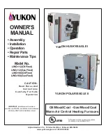
Fig. 16—Furnace Wiring Diagram

A00304

PCB

BLOWER OFF DELAY

SELECTION CHART

90 SEC

135 SEC

180 SEC

225 SEC

GVR

HI/LO

RELAY

SEC-1

SEC-2

PL1

3 2 1

6 5 4
9 8 7

LED

TEST/TWIN

BLOWER

OFF

DELAY

G
R
Y

W
C

HUM

HSIR

IDR

BLWR

BLOWER

SPEED

SELECT

FU1

COOL

HEAT

L2

PL3

PL2

VAC

120

L1

PR1

1

2

1
2
3

PR2

24 VAC-3A

FUSE

SPARE-2

SPARE-1

EAC-1

EAC-2

C

1.

5

 A

M

P

1

2

PL5

WHT

BLK

WHT

WHT

BL

K

BL

K

HSI

BLK

WHT

WHT   (COM)

RED   (LO)

BLU (MED LO)

NOTE #7

OL

START

BLWM

YEL (MED HI)

BLK  (HI)

BRN

BRN

TR

A

N

BLU

RED

BLK

WHT

WHT (COM)

CAP

RED

RED

ORN

FUSED DISCONNECT

SWITCH (WHEN REQ’D)

NOTE #4

FU2

BLK

WHT

JB

LEGEND

ALS

AUXILIARY LIMIT SWITCH, OVERTEMP. -MANUAL RESET, SPST-(N.C.)

BLWR

BLOWER MOTOR RELAY, SPST-(N.O.)

BLWM BLOWER MOTOR
BVSS

BLOCKED VENT SHUTOFF SWITCH, SPST - (N.C.)

CAP

CAPACITOR

CPU

MICROPROCESSOR AND CIRCUITRY

DSS

DRAFT SAFEGUARD SWITCH

EAC-1

ELECTRONIC AIR CLEANER CONNECTION (115 VAC 1.5 AMP MAX.)

EAC-2

ELECTRONIC AIR CLEANER CONNECTION (COMMON)

FL

FUSIBLE LINK

FRS

FLAME ROLLOUT SW. -MANUAL RESET, SPST-(N.C.)

FSE

FLAME PROVING ELECTRODE

FU1

FUSE, 3 AMP, AUTOMOTIVE BLADE TYPE, FACTORY INSTALLED

FU2

FUSE OR CIRCUIT BREAKER CURRENT INTERRUPT DEVICE
(FIELD INSTALLED & SUPPLIED)

GV

GAS VALVE-REDUNDANT OPERATORS

GVR

GAS VALVE RELAY, DPST-(N.O.)

HI/LO

BLOWER MOTOR SPEED CHANGE RELAY, SPDT

HSI

HOT SURFACE IGNITOR (115 VAC)

HSIR

HOT SURFACE IGNITOR RELAY, SPST-(N.O.)

HUM

24VAC HUMIDIFIER CONNECTION (.5 AMP. MAX.)

IDM

INDUCED DRAFT MOTOR

IDR

INDUCED DRAFT RELAY, SPST-(N.O.)

ILK

BLOWER ACCESS PANEL INTERLOCK SWITCH, SPST-(N.O.)

JB

JUNCTION BOX

LED

LIGHT-EMITTING DIODE FOR STATUS CODES

LGPS

LOW GAS PRESSURE SWITCH, SPST-(N.O.)

LS

LIMIT SWITCH, AUTO RESET, SPST(N.C.)

OL

AUTO-RESET INTERNAL MOTOR OVERLOAD TEMP. SW.

PCB

PRINTED CIRCUIT BOARD

PL1

9-CIRCUIT CONNECTOR

PL2

2-CIRCUIT PCB CONNECTOR

PL3

3-CIRCUIT IDM CONNECTOR

PL5

2-CIRCUIT HSI/PCB CONNECTOR

PRS

PRESSURE SWITCH, SPST-(N.O.)

TEST/TWIN

COMPONENT TEST & TWIN TERMINAL

TRAN

TRANSFORMER-115VAC/24VAC

JUNCTION

UNMARKED TERMINAL

PCB TERMINAL

FACTORY WIRING (115VAC)

FACTORY WIRING (24VAC)

FIELD WIRING (115VAC)

FIELD WIRING (24VAC)

CONDUCTOR ON PCB

FIELD WIRING TERMINAL

FIELD GROUND

EQUIPMENT GROUND

FIELD SPLICE

PLUG RECEPTACLE

L1

L2

L1

BLWR

HI/LO

TO 115VAC FIELD DISCONNECT

NOTE #4

EQUIPMENT GROUND

SPARE-2

HEAT

SPARE-1

COOL

NOTE #7

COM

HSIR

EAC-1

START

OL

COM

HI

MED HI

MED LO

LO

BLWM

SCHEMATIC DIAGRAM

(NATURAL GAS & PROPANE)

EAC-2

1

1

HSI

2

PL5

2

PL2

3 PL3

PR2

115VAC

PR1

TRAN

24VAC

1

2

IDR

TEST/TWIN

FU1

NOTE #6

CAP

L2

PL1

8

FSE

9

6

5

CPU

HSIR

IDR

BLWR

Y

G

C

R

W

GVR-2

SEC-1

HI/LO

GVR

SEC-2

NOTES:

322869-101 REV. H

1. If any of the original equipment wire is replaced use wire rated for 105

°

C.

2. Inducer (IDM) and blower (BLWM) motors contain internal auto-reset thermal overload switches (OL).
3. Blower motor speed selections are for average conditions, see installation instructions for details on

optimum speed selection.

4. Use only copper wire between the disconnect switch and the furnace junction box (JB).
5. This wire must be connected to furnace sheetmetal for control to detect flame.
6. Replace only with a 3 amp fuse.
7. Yellow lead not on all motors.
8. Blower-on delay, gas heating 45 seconds, cooling or heat pump 2 seconds.
9. Blower-off delay, gas heating 90, 135, 180 or 225 seconds, cooling or heat pump 90 seconds.

(135 seconds only on some models)

10. Ignition-lockout will occur after four consecutive unsuccessful trials-for-ignition. Control will auto-reset

after three hours.

11. When used, auxiliary limit switch (ALS) is on some downflow models only. When used, FL is on

upflow models only.

12. Some models may have spade quick connect terminals.
13. Factory connected when LGPS is not used.
14. Factory connected when BVSS is not used. BVSS used when Chimney Adapter Accessory Kit is

installed.

15. Gas valve leads are interchangeable on single stage valves.

BL

K

OM

SW2

SW1

OM

3

4

7

1

OM

HUM

IDM

ILK

DSS

BVSS

PRS

ILK

L1

NEUTRAL

IDM

(WHEN USED)

NOTE #14

NOT USED

NOT USED

NOT USED

FSE

BLU

PRS

DSS

BVSS

(WHEN USED)

NOTE #14

WHT

LS

FL

(NOT ON ALL MODELS)

NOTE #9

FRS1

FRS2

LS

FL

NOTE #12

ORN

ORN

ORN

ALS

(WHEN USED)

ORN

NOTE #11

LGPS

(WHEN USED)

NOTE #13

NOTE #14

NOTE #11

2

GVR-1

NOTE #14

ALS

(WHEN USED)

(WHEN USED)

NOTE #13

LGPS

(WHEN USED)

NOTE #13

YEL

FRS1

FRS2

(WHEN USED) NOTE #11

GRN/YEL

GRN/YEL

GND

NOTE #5

GRN/YEL

NOTE #5

GRN/YEL

NOTE #15

NOTE #15

GV

GV

14

Summary of Contents for 58RAV 170 Series

Page 1: ... literature on tags and on labels attached to or shipped with the unit and other safety precautions that may apply In the United States follow all safety codes including the National Fuel Gas Code NFGC NFPA 54 1999 ANSI Z223 1 1999 and the Installation Standards Warm Air Heating and Air Condition ing Systems NFPA 90B ANSI NFPA 90B In Canada refer to the CAN CGA B149 1 and 2 M95 National Standard o...

Page 2: ...o be installed in a furnace follow items 1 through 5 before bringing the control or yourself into contact with the furnace Put all used AND new controls into containers before touching ungrounded objects 7 An ESD service kit available from commercial sources may also be used to prevent ESD damage Table 1 Dimensions In UNIT SIZE A D E VENT CONN SHIP WT LB 050 08 14 3 16 12 9 16 12 11 16 4 121 050 1...

Page 3: ...inances especially those that may not have kept pace with changing residential construction practices We require these instructions as a minimum for a safe installation Application of this furnace should be indoors with special attention given to vent sizing and material gas input rate air temperature rise and unit sizing Improper installation or misapplication of the furnace can require excessive...

Page 4: ...e ample space for servicing and cleaning Always comply with the minimum fire protection clearances shown on the unit rating plate This furnace shall not be installed directly on carpeting tile or any combustible material other than wood flooring The furnace may be installed on combustible flooring when installed with the accessory downflow subbase which is available from your distributor or branch...

Page 5: ...jacent to furnace all air for combustion must come from outdoors 2 Air from outside the structure requires 1 of the following methods a If combustion air is taken from outdoors through 2 vertical ducts the openings and ducts MUST have at least 1 sq in of free area per 4000 Btuh of total input for all equipment within the confined space See Fig 4 and Table 2 b If combustion air is taken from outdoo...

Page 6: ...The return air duct must be connected to return air opening inlet provided as shown in Fig 1 DO NOT cut into casing sides or back to attach any portion of return air duct Bypass humidifier connec tions should be made at ductwork or coil casing sides exterior to furnace Fig 3 Confined Space Air for Combustion and Ventilation from an Unconfined Indoor Space A93387 RETURN AIR 6 MIN FRONT SUPPLY AIR V...

Page 7: ...rking platform on location where all required furnace clearances are met See Fig 2 and 8 INSTALL FURNACE 1 Position furnace in desired location 2 Connect gas supply pipe See Fig 8 for typical piping entry 3 Install field supplied filter retainers as indicated in Fig 11 and Table 4 before connecting return air duct to furnace Table 3 Opening Dimensions In FURNACE CASING WIDTH APPLICATION PLENUM OPE...

Page 8: ...ed on a Combustible Floor A96284 CD5 OR CK5 COIL ASSEMBLY OR KCAKC COIL BOX FURNACE SHEET METAL PLENUM FLOOR OPENING COMBUSTIBLE FLOORING Fig 8 Typical Attic Installation A97516 30 IN MIN WORK AREA 6 MIN TYPE B VENT GAS ENTRY 24 24 SHEET METAL SEDIMENT TRAP MANUAL SHUTOFF GAS VALVE LINE CONTACT ONLY PERMISSIBLE BETWEEN LINES FORMED BY INTERSECTIONS OF THE TOP AND TWO SIDES OF THE FURNACE JACKET AN...

Page 9: ...ect to the furnace and to the meter If a flexible connector is required or allowed by the authority having jurisdiction black iron pipe shall be installed at the gas valve and extend a minimum of 2 in outside the furnace casing Use the proper length of pipes to avoid stress on the gas control manifold Failure to follow this warning could result in a gas leak causing fire explosion personal injury ...

Page 10: ...r 115 v wiring If polarity is incorrect control center status code indicator light will flash rapidly and furnace will not operate Fig 10 Horizontal Crawlspace Installation on Hanger Rods A96633 NOTES ANGLE IRON OR EQUIVALENT ROD LOCATION USING DIMPLE LOCATORS SEE DIMENSIONAL DWG FOR LOCATIONS 3 8 IN ROD 1 A 1 In clearance minimum between top of furnace and combustible material 2 The entire length...

Page 11: ... or controller manufacturer s instructions for proper connec tion A failure to follow this warning could result in fire NOTE A field supplied 115 v controlled relay connected to EAC terminals may be added if humidifier operation is desired during blower operation Step 11 Venting Refer to the national or local installation code such as NFGC in the United States or the NSCNGPIC in Canada for proper ...

Page 12: ...own for proper operation Some thermostats require a C terminal connection as shown If any of the original wire as supplied must be replaced use same type or equivalent wire W Y GND THERMOSTAT TERMINALS 1 2 3 Fig 14 Furnace Control A99255 HUMIDIFIER TERMINAL 24 VAC 0 5 AMP MAX LED OPERATION DIAGNOSTIC LIGHT HARNESS CONNECTOR 24 V TRANSFORMER SEC 2 SPARE 1 SPARE 2 EAC 1 EAC ELECTRONIC AIR CLEANER TE...

Page 13: ...t sensed the control closes the gas valve and repeats the ignition cycle NOTE Ignition sequence will repeat 3 additional times before a lockout occurs Lockout automatically resets after 3 hrs or can be manually reset by turning 115v off not at thermostat for 3 sec minimum then on again f Blower on delay Forty five sec after burner flame is proven the blower motor is energized on heating speed Simu...

Page 14: ...VAC CONDUCTOR ON PCB FIELD WIRING TERMINAL FIELD GROUND EQUIPMENT GROUND FIELD SPLICE PLUG RECEPTACLE L1 L2 L1 BLWR HI LO TO 115VAC FIELD DISCONNECT NOTE 4 EQUIPMENT GROUND SPARE 2 HEAT SPARE 1 COOL NOTE 7 COM HSIR EAC 1 START OL COM HI MED HI MED LO LO BLWM SCHEMATIC DIAGRAM NATURAL GAS PROPANE EAC 2 1 1 HSI 2 PL5 2 PL2 3 PL3 PR2 115VAC PR1 TRAN 24VAC 1 2 IDR TEST TWIN FU1 NOTE 6 CAP L2 PL1 8 FSE...

Page 15: ...ignal is present at control Component test sequence is as follows a Momentarily jumper TEST and COM 24V terminals until LED goes off b LED will display previous status 4 times c Inducer motor starts and continues to run for entire com ponent test d Hot surface igniter is energized for 15 sec then de energized e Blower motor operates on cooling speed for 10 sec then stops f Blower motor operates on...

Page 16: ... 43 2 8 43 2 9 43 3 0 43 3 1 4500 1025 43 2 6 43 2 6 43 2 7 43 2 8 43 2 9 ALTITUDE RANGE FT AVG GAS HEAT VALUE AT ALTITUDE BTU CU FT SPECIFIC GRAVITY OF NATURAL GAS 0 58 0 60 0 62 0 64 0 66 Orifice No Manifold Pressure Orifice No Manifold Pressure Orifice No Manifold Pressure Orifice No Manifold Pressure Orifice No Manifold Pressure U S A Only 750 42 3 4 42 3 6 42 3 7 42 3 8 41 3 5 775 42 3 2 42 3...

Page 17: ...43 2 4 43 2 5 43 2 5 43 2 6 850 43 2 2 43 2 2 43 2 3 43 2 4 43 2 5 875 43 2 0 43 2 1 43 2 2 43 2 3 43 2 3 ALTITUDE RANGE FT AVG GAS HEAT VALUE AT ALTITUDE BTU CU FT SPECIFIC GRAVITY OF NATURAL GAS 0 58 0 60 0 62 0 64 0 66 Orifice No Manifold Pressure Orifice No Manifold Pressure Orifice No Manifold Pressure Orifice No Manifold Pressure Orifice No Manifold Pressure U S A Only 625 43 3 4 43 3 6 43 3...

Page 18: ...te cu ft hr X heating value Btu cu ft using natural gas heating value from local gas utility supplier EXAMPLE 0 2000 ft altitude Btu heating input Btu cu ft X cu ft hr Heating value of gas 1050 Btu cu ft Time for 1 revolution of 2 cu ft dial 82 sec Gas rate 88 cu ft hr from Table 9 Btu heating input 88 X 1050 92 400 Btuh In this example the orifice size and manifold pressure adjustment is within 2...

Page 19: ...e blower motor has started See the thermostat manufacturer s instructions for adjusting the heat anticipator and for varying the heating cycle length Table 9 Gas Rate Cu Ft Hr SECONDS FOR 1 REVOLUTION SIZE OF TEST DIAL SECONDS FOR 1 REVOLUTION SIZE OF TEST DIAL 1 cu ft 2 cu ft 5 cu ft 1 cu ft 2 cu ft 5 cu ft 10 11 12 13 14 360 327 300 277 257 720 655 600 555 514 1800 1636 1500 1385 1286 50 51 52 5...

Page 20: ...ire harness c Turn on 115 v power to furnace d Set thermostat to call for heat and wait 1 minute When pressure switch is functioning properly hot surface igniter should NOT glow and control diagnostic light flashes a status code 31 If hot surface igniter glows when inducer motor is disconnected shut down furnace immediately Determine reason pressure switch did not function properly and correct con...

Page 21: ...cal Codes ____________ 1 4 in Upward Slope ____________ Joints Secure ____________ See Attached Vent Table Instructions CHECKLIST START UP ____________ Gas Input Rate Set Within 2 percent of Rating Plate ____________ Temperature Rise Adjusted ____________ Thermostat Anticipator Setting Adjusted or ____________ Thermostat Cycle Rate 3 cycles per Hr CHECK SAFETY CONTROLS OPERATION ____________ Prima...

Page 22: ...22 ...

Page 23: ...23 ...

Page 24: ...e Training plus hands on the products in our labs can mean increased confidence that really pays dividends in faster troubleshooting fewer callbacks Course descriptions and schedules are in our catalog CALL FOR FREE CATALOG 1 800 962 9212 Packaged Service Training Classroom Service Training Copyright 2000 CARRIER Corp 7310 W Morris St Indianapolis IN 46231 58ra16si Manufacturer reserves the right ...

Reviews: