


Step 5—Gas Piping
Gas piping must be installed in accordance with national and local
codes. Refer to the current edition of the NFGC.
Canadian installations must be installed in accordance with the
NSCNGPIC and all authorities having jurisdiction.
Gas piping shall be of such size and so installed as to provide a
supply of gas sufficient to meet maximum demands without undue
loss of pressure between gas meter and furnace. It is recommended
that the gas supply line be a separate line running directly from
meter to furnace, unless existing gas line is of ample capacity.
Refer to Table 3 for recommended gas pipe sizing. Risers must be
used to connect to furnace and to meter.
Support all piping with appropriate straps, hangers, etc. Use a
minimum of 1 hanger every 72 in.
Joint compounds (pipe dope) should be applied sparingly and only
to male threads of joints. This pipe dope must be resistant to the
action of propane gas.
NOTE:
In order to make proper adjustments, minimum and
maximum gas supply pressure limits shown on rating plate must
not be exceeded.
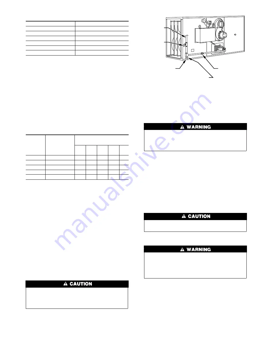
Install a sediment trap in riser leading to furnace. The trap can be
installed by connecting a tee to riser leading to furnace, so that the
straight-through section of tee is vertical.
Then connect a capped nipple into lower end of tee. The capped
nipple should extend below the level of gas controls. Place a
ground joint union between gas control manifold and manual gas
shutoff valve. (See Fig. 4.)
If a flexible connector is required or allowed by the authority
having jurisdiction, black iron pipe shall be installed at the
gas valve and extend a minimum of 2 in. outside the furnace
casing.
An accessible manual shutoff valve MUST be installed upstream
of furnace gas controls and within 72 in. of furnace. A 1/8-in. NPT
plugged tapping, accessible for test gage connection, MUST be
installed immediately upstream of gas supply connection to
furnace and downstream of manual shutoff valve. (The manifold
pressure tap on gas control meets this requirement.)
Use the proper length of pipes to avoid stress on the gas
control manifold. A failure to follow this warning could result
in a gas leak resulting in a fire, explosion, personal injury, or
death.
Before any system of gas piping is finally put into service, it
should be carefully tested to determine if it is gas tight. The piping
must stand a pressure of 6 in. of mercury for a period of 10 minutes
or as required by local authority.
Piping should be pressure tested in accordance with local and
national plumbing and gas codes before furnace has been attached.
If test pressure exceeds 0.5 psig (14-in. wc), the gas supply pipe
must be disconnected from furnace and capped before pressure
test. If test pressure is equal to or less than 0.5 psig (14-in. wc),
close manual shutoff valve located on gas valve before pressure
test. It is recommended that the ground joint union be loosened
before pressure testing.
Use a backup wrench when connecting the gas pipe to the
furnace to avoid damaging gas controls.
After all connections have been made, purge the lines and check
for leakage.
Never purge a line into a combustion chamber. Never use
matches, candles, flame, or other sources of ignition for the
purpose of checking leakage. Use a soap-and-water solution
to check for leakage. Failure to follow this warning could
result in a fire, explosion, personal injury, or death.
Table 2—Filter Size (In.)
UNIT SIZE
FILTER SIZE
050-12
13 X 23
075-12
13 X 23
075-16
13 X 23
100-16
16-1/2 X 23
100-20
16-1/2 X 23
125-20
20 X 23
Table 3—Maximum Capacity of Pipe*
NOMINAL
IRON
PIPE
SIZE
(IN.)
INTERNAL
DIAMETER (IN.)
LENGTH OF PIPE (FT)
10
20
30
40
50
1/2
0.622
175
120
97
82
73
3/4
0.824
360
250
200
170
151
1
1.049
680
465
375
320
285
1-1/4
1.380
1400
950
770
660
580
1-1/2
1.610
2100
1460
1180
1993
900
*Cu ft of gas per hr for gas pressures of 0.5 psig (14-in. wc) or less, and a
pressure drop of 0.5-in. wc (based on a 0.60 specific gravity gas). Ref: Table
10-2 NFPA 54-1992.
Fig. 4—Typical Gas Piping
A96071
GAS
SUPPLY
MANUAL
SHUTOFF
VALVE
SEDIMENT
TRAP
UNION
THIS DRIP LEG MUST BE
INSTALLED WITH THE PIPE
CAP A MINIMUM OF 1 IN.
FROM FLOOR TO PERMIT
REMOVAL
7