


needed (see item 4). Refer to NFGC Appendix F,
Table F-4 for proper orifice sizing at high altitudes.
(2.) High-altitude installations (Canada only)—The Cana-
dian ratings are approved for altitudes up to 2000 ft for
natural and propane gases. High-altitude ratings are
from 2000 ft to 4500 ft above sea level. See Table 7
for nominal burner orifice size. High-altitude input
ratings include a 10 percent derate as required by
Canadian standards.
h. Proceed to item 3 to adjust manifold pressure.
3. Adjust gas input.
NOTE:
The gas valve has been nominally set at 3.5-in. wc for
natural gas.
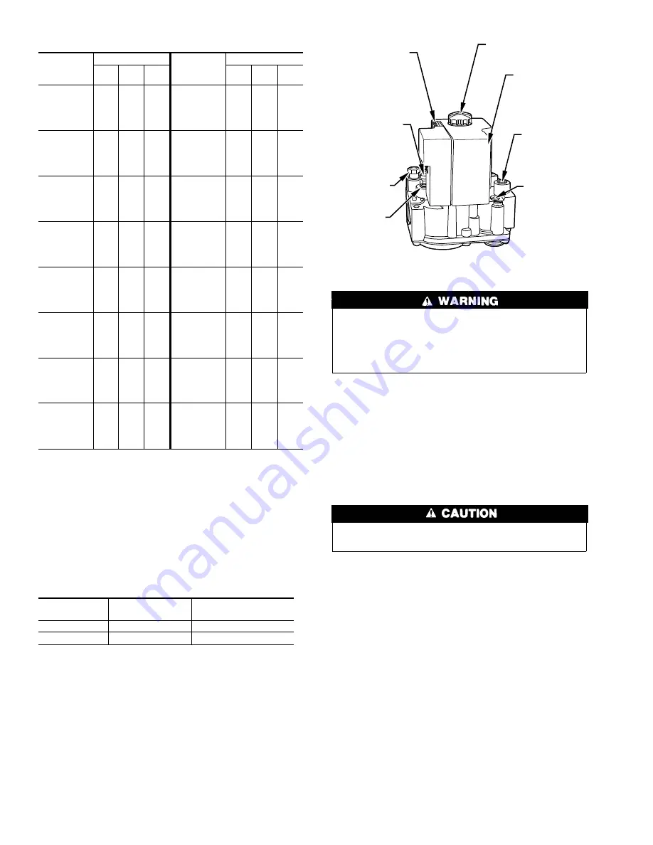
a. Remove cap that conceals adjustment screw for gas valve
regulator. (See Fig. 15.)
b. Turn adjusting screw either counterclockwise (out) to
decrease input rate or clockwise (in) to increase rate. When
adjusting input rate, DO NOT set manifold pressure less
than 3.2-or more than 3.8-in. wc for natural gas. Make any
major adjustments by changing main burner orifices.
DO NOT redrill orifices. Improper drilling (burrs, out-of-
round holes, etc.) can cause excessive burner noise and
misdirection of burner flames. This can result in flame
impingement of the burners and heat exchangers causing
failures.
NOTE:
If orifice hole appears damaged or it is suspected to have
been redrilled, check the orifice hole with the correct size
numbered drill bit. Never redrill an orifice. A burr-free and
squarely aligned orifice hole is essential for proper flame charac-
teristics.
c. Measure adjusted gas input rate using method outlined in
item 2.
d. Replace cap that conceals gas valve regulator adjustment
screw.
Be sure burner enclosure front is in place after adjustments
have been made.
e. Look through openings in burner enclosure and check
burner flame. The main burner flame should be clear blue,
almost transparent. (See Fig. 16.)
4. Change burner orifice (if necessary).
The furnace is supplied with standard orifices for the gas
shown on rating plate. If orifices need to be changed to
achieve proper input rate, proceed as follows:
a. Remove manifold pipe cover and burner removal cover/air
inlet plate.
b. Remove manifold retention plate.
c. Pull manifold/burner assembly out past support pins and
remove assembly.
NOTE:
It is only necessary to remove 1 manifold retention plate
to gain access to burners.
d. Remove burners from assembly and change orifices as
required.
e. Reinstall assembly by reversing the procedure in items a
through d making sure that assembly is securely mounted
under manifold retention plate on opposite side of unit.
Table 6—Gas Rate Cu Ft/Hr
SECONDS
FOR 1
REVOLUTION
SIZE OF TEST DIAL
SECONDS
FOR 1
REVOLUTION
SIZE OF TEST DIAL
1
cu ft
2
cu ft
5
cu ft
1
cu ft
2
cu ft
5
cu ft
10
11
12
13
14
360
327
300
277
257
720
655
600
555
514
1800
1636
1500
1385
1286
50
51
52
53
54
72
71
69
68
67
144
141
138
136
133
360
355
346
340
333
15
16
17
18
19
240
225
212
200
189
480
450
424
400
379
1200
1125
1059
10 0
947
55
56
57
58
59
65
64
63
62
61
131
129
126
124
122
327
321
316
310
305
20
21
22
23
24
180
171
164
157
150
360
343
327
313
300
900
857
818
783
750
60
62
64
66
68
60
58
56
54
53
120
116
112
109
106
300
290
281
273
265
25
26
27
28
29
144
138
133
129
124
288
277
267
257
248
720
692
667
643
621
70
72
74
76
78
51
50
48
47
46
103
100
97
95
92
257
250
243
237
231
30
31
32
33
34
120
116
113
109
106
240
232
225
218
212
600
581
563
545
529
80
82
84
86
88
45
44
43
42
41
90
88
86
84
82
225
220
214
209
205
35
36
37
38
39
103
100
97
95
92
206
200
195
189
185
514
500
486
474
462
90
92
94
96
98
40
39
38
38
37
80
78
76
75
74
200
196
192
188
184
40
41
42
43
44
90
88
86
84
82
180
176
172
167
164
450
439
429
419
409
100
102
104
106
108
36
35
35
34
33
72
71
69
68
67
180
178
173
170
167
45
46
47
48
49
80
78
76
75
73
160
157
153
150
147
400
391
383
375
367
110
112
116
120
33
32
31
30
65
64
62
60
164
161
155
150
Table 7—Canadian Orifice Size
GAS
SEA LEVEL
0-2000 FT
HIGH ALTITUDE
2000-4500 FT
Natural
42
43
Propane
54
55
Fig. 15—Honeywell SmartValve
A96079
IGNITION SYSTEM
CONTROL KNOB
IGNITION
MODULE
INLET
PRESSURE
TAP
IGNITOR
CONNECTOR
PILOT
ADJUSTMENT
(UNDER CAP
SCREW)
PILOT
OUTLET
MANIFOLD
PRESSURE
TAP
GAS
PRESSURE
REGULATOR
ADJUSTMENT
(UNDER CAP
SCREW)
16