


The cabinet must have an uninterrupted or unbroken ground
according to National Electrical Code, ANSI/NFPA 70-1996,
Canadian Electrical Code, CSA C22.1, or local codes to
minimize personal injury if an electrical fault should occur.
This ground may consist of electrical wire or conduit ap-
proved for electrical ground when installed in accordance
with existing electrical codes. Do not use gas piping as an
electrical ground. Failure to follow this warning could result
in an electrical shock, fire, or death.
NOTE:
Proper polarity must be maintained for 115-v wiring for
ignition control to function properly. Connect "hot" wire H and
"ground" wire G as shown in Fig. 12.
If manual disconnect switch is to be mounted on the furnace,
select a location where a drill or fastener will not contact
electrical or gas components.
Step 2—24-v Wiring
Make field 24-v thermostat connections at the 24-v terminal block.
Connect Y terminal as shown in Fig. 10 for proper cooling
operation. The 24-v control board is marked for easy connection of
field wiring. (See Fig. 11.)
NOTE:
Use AWG No. 18 color coded copper thermostat wire for
lengths up to 100 ft. For wire lengths over 100 ft, use AWG No.
16 wire.
Step 3—Accessories
Install accessories per manufacturer’s instructions. Other than
wiring for thermostat, a minimum of type T wire (63°F/35°C rise)
must be used.
1. Electronic Air Cleaner (EAC)
Two 1/4-in. quick-connect terminals marked EAC and N are
provided for EAC connection. (See Fig. 11.) These terminals
are energized with 115v (0.5-amp maximum) during blower
motor operation.
2. Humidifier (HUM)
Two 1/4-in. quick-connect terminals marked HUM and N are
provided for 115-v humidifier connection. (See Fig. 11.)
These terminals are energized with 115v (0.5-amp maximum)
during any call for heat.
Cycle test furnace and accessories twice to ensure proper opera-
tion.
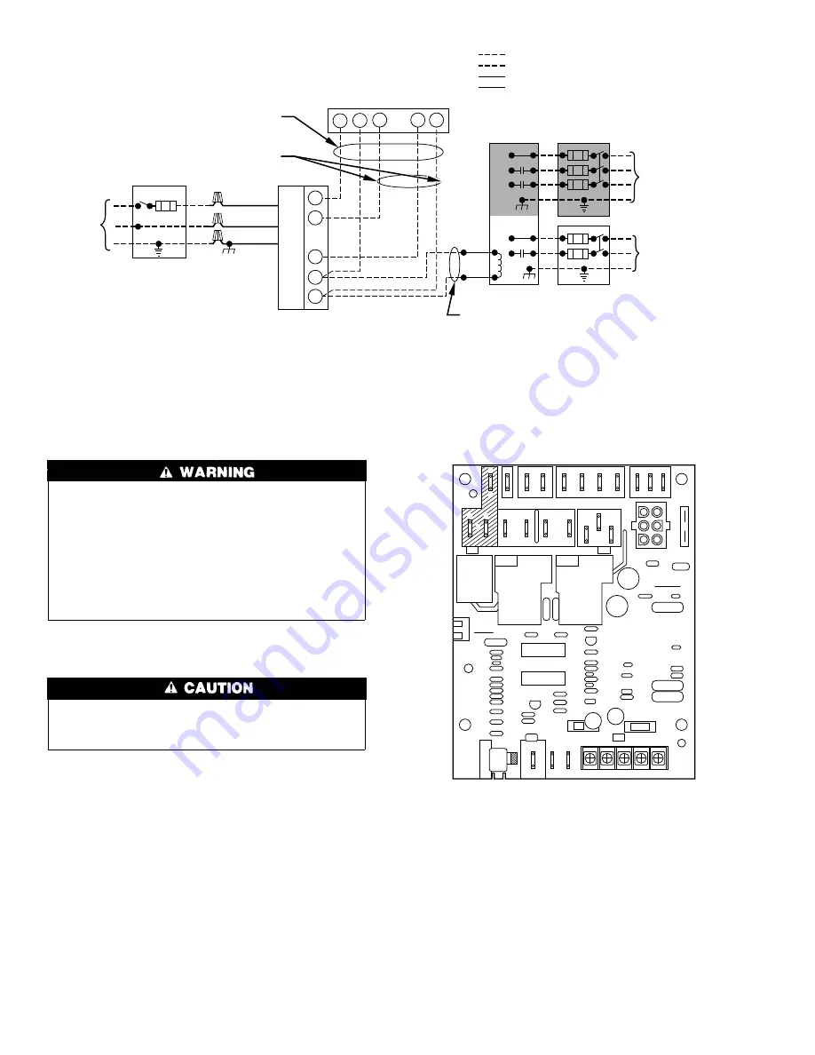
Fig. 10—Heating and Cooling Application Wiring Diagram
A96104
1. Connect Y-terminal as shown for proper cooling operation.
2. If any of the original wire, as supplied, must be replaced,
use same type or equivalent wire.
3. Proper polarity must be maintained for 115-volt wiring.
4. Some thermostats require a "C" terminal connection as shown.
NOTE :
115-VOLT
FIELD-SUPPLIED
FUSED DISCONNECT
24-VOLT
TERMINAL
BLOCK
THREE-WIRE
HEATING
ONLY
FIVE
WIRE
NOTE 4
THERMOSTAT
TERMINALS
FIELD-SUPPLIED
FUSED DISCONNECT
CONDENSING
UNIT
TWO
WIRE
R
G
C
W
R
C
G
Y
GND
GND
FIELD 24-VOLT WIRING
FIELD 115-, 208/230-, 460-VOLT WIRING
FACTORY 24-VOLT WIRING
FACTORY 115-, 208/230-, 460-VOLT WIRING
208/230- OR
460-VOLT
THREE
PHASE
208/230-
VOLT
SINGLE
PHASE
W
Y
GND
GND
GND
115-VOLT
SINGLE
PHASE
GND
Fig. 11—Control Board
A96103
C
G
UNUSED
DI
1
SPEED
UP
N
NEUTRAL
2
3
4
C
XFMR
SEC
X
X
MOTOR
LEADS
Y W
R
S
3
2
HUM
EAC
C
Y
N
N
CIR
T
W
I
N
CONT
HEAT
5
COOL
BLWR
1
S
10