


between the thermostat and the unit. If the thermostat is located
more than 100 ft. from the unit (as measured along the control
voltage wires), use no. 16 AWG color-coded, insulated (35 C
minimum) wires.
STANDARD CONNECTION
Remove knockout hole located in the electric heat panel adjacent
to the control access panel. See Fig. 2 & 3. Remove the rubber
grommet from the installer’s packet (included with unit) and install
grommet in the knockout opening. Provide a drip loop before
running wire through panel.
Run the low-voltage leads from the thermostat, through the inlet
hole, and into unit low-voltage splice box.
Locate five 18-gage wires leaving control box. These low-voltage
connection leads can be identified by the colors red, green, yellow,
brown, and white (See Fig. 10). Ensure the leads are long enough
to be routed into the low-voltage splice box (located below right
side of control box). Stripped yellow wire is located in connection
box. Route leads through hole in bottom of control box and make
low-voltage connections (See Fig. 10). Secure all cut wires, so that
they do not interfere with operation of unit.
TRANSFORMER PROTECTION
The
transformer
is of the energy-limiting type. It is set to
withstand a 30-second overload or shorted secondary condition.
PRE-START-UP
FIRE, EXPLOSION, ELECTRICAL SHOCK HAZARD
Failure to observe the following warnings could result in
serious personal injury:
1. Follow recognized safety practices and wear protective
goggles when checking or servicing refrigerant system.
2. Relieve and recover all refrigerant from system before
touching or disturbing anything inside terminal box if
refrigerant leak is suspected around compressor terminals.
3. Never attempt to repair soldered connection while refrig-
erant system is under pressure.
4. Do not use torch to remove any component. System
contains oil and refrigerant under pressure. To remove a
component, wear protective goggles and proceed as fol-
lows:
a. Shut off electrical power to unit.
b. Relieve and reclaim all refrigerant from system using
both high- and low-pressure ports.
c. Cut component connecting tubing with tubing cutter and
remove component from unit.
d. Carefully unsweat remaining tubing stubs when neces-
sary. Oil can ignite when exposed to torch flame.
Proceed as follows to inspect and prepare the unit for initial
startup:
1. Remove access panel.
2. Read and follow instructions on all WARNING, CAUTION,
and INFORMATION labels attached to, or shipped with, unit.
3. Make the following inspections:
a. Inspect for shipping and handling damages such as broken
lines, loose parts, disconnected wires, etc.
b. Inspect for oil at all refrigerant tubing connections and on
unit base. Detecting oil generally indicates a refrigerant
leak. Leak test all refrigerant tubing connections using
electronic leak detector, halide torch, or liquid-soap solu-
tion. If a refrigerant leak is detected, see Check for
Refrigerant Leaks section.
c. Inspect all field- and factory-wiring connections. Be sure
that connections are completed and tight.
d. Ensure electrical wiring does not contact refrigerant tubes
or sharp metal edges.
e. Inspect coil fins. If damaged during shipping and handling,
carefully straighten fins with a fin comb.
Verify the following conditions:
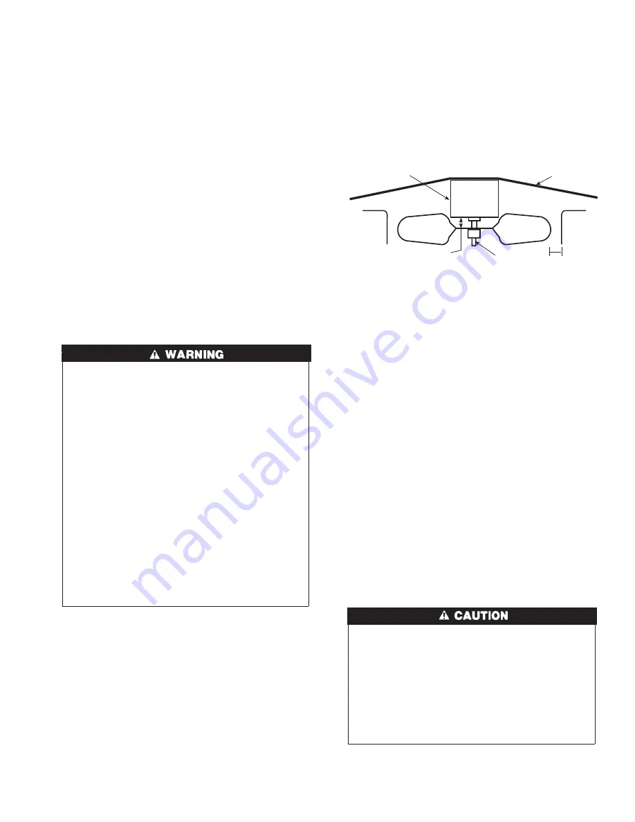
a. Make sure that condenser-fan blade is correctly positioned
in fan orifice. Leading edge of condenser-fan blade should
be 1/2 in. maximum from fan orifice (See Fig. 11).
b. Make sure that air filter(s) is in place.
c. Make sure that condensate drain trap is filled with water to
ensure proper drainage.
d. Make sure that all tools and miscellaneous loose parts have
been removed.
START-UP
CHECK FOR REFRIGERANT LEAKS
Proceed as follows to locate and repair a refrigerant leak and to
charge the unit:
1. Locate leak and make sure that refrigerant system pressure has
been relieved and reclaimed from both high- and low-pressure
ports.
2. Repair leak following accepted practices. NOTE: Install a
filter drier whenever the system has been opened for repair.
3. Add a small charge of R-22 refrigerant vapor to system and
leak-test unit.
4. Recover refrigerant from refrigerant system and evacuate to
500 microns if no additional leaks are not found.
5. Charge unit with R-22 refrigerant, using a volumetric-
charging cylinder or accurate scale.
Refer to unit rating plate
for required charge.
Be sure to add extra refrigerant to
compensate for internal volume of filter drier.
START UP COOLING SECTION AND MAKE ADJUST-
MENTS
EQUIPMENT DAMAGE HAZARD
Failure to follow this caution may result in unit component
damage.
Complete the required procedures given in the Pre-Start- Up
section before starting the unit. Do not jumper any safety
devices when operating the unit. Do not operate the compres-
sor when the outdoor temperature is below 40°F (unless
accessory low-ambient kit is installed). Do not rapid-cycle the
compressor. Allow 5 minutes between “on” cycles to prevent
compressor damage.
CHECKING COOLING CONTROL OPERATION
Start and check the unit for proper cooling control operation as
follows:
Fig. 11—Fan Blade Clearance
C99009
FAN GRILLE
MOTOR
1/8" MAX BETWEEN
MOTOR AND FAN HUB
MOTOR SHAFT
1/2˝
11


