background image

Packaged rooftop units 

with integrated gas burner

20

Refrigerant

Qualifi ed personnel must perform a periodic control to air tightness 

depending on the refrigerant load, in accordance with the regulation 

(CE) Nº 842/2006.

It is important not to ever forget that the cooling systems contain 

liquids and vapours under pressure. The service pressure of R-410A is 

approximately 1.5 times higher than that of R-407c.

-  All necessary precautions must be taken during the partial opening 

of the cooling circuit. This opening entails the discharge of a certain 

amount of refrigerant to the atmosphere. It is essential to limit to its 

minimum this amount of lost refrigerant by pumping and isolating the 

load in some other part of the circuit.

- The refrigerant fl uid at low temperature can cause infl ammatory 

injuries similar to burns when contacting the skin or eyes. Always 

use protection glasses, gloves, etc. when opening ducts that may 

contain liquids. 

-  The refrigerant in excess must be stored in appropriate containers 

and the amount of refrigerant stored at the technical rooms must be 

limited. 

-  Refrigerant barrels and deposits must be handled with precaution 

and visible warning signs must be placed to attract attention over 

the risks of intoxication, fi re and explosion linked to the refrigerant. 

-  At the end of its useful life, the refrigerant must be retrieved and 

recycled as per the current regulations.

Gas Burner

Oil

-  Check the oil level and aspect. In case of a colour change, check 

the oil quality using a contamination test. 

-  In the case of the presence of acid, water or metallic particles, replace 

the affected circuit oil, as well as the dehydrant fi lter. 

-  In the event of an oil charge change, only new oil will be used, which 

will be identical to the original oil and taken from a can tightly closed 

until the moment of the charge.

Note:

 Both the oil type as well as the volume needed for each model 

are stated in the Technical characteristic tables in chapter 3.

Caution: 

Before starting any maintenance operations 

ensure that the supply of gas and electricity have been 

turned off.

V-220004

Only qualifi ed staff are allowed to undertake maintenance 

tasks or resolve a breakdown.

Pay attention to the temperatures of some components after 

operation. They could be very high (exchanger, chimney, 

etc).

Hazard:

 Never use a naked fl ame whilst checking the burner. 

Never store fl ammable material in the machine room.

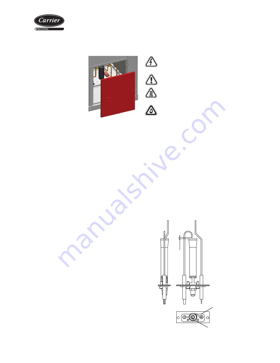
1. The ignition, fl ame detector and the electrodes

Disassemble the set and clean the steel grille and the nozzle with a 

blast of compressed air. Check that the ceramic is intact and remove 

any oxide residue from the metal parts of the electrodes using emery 

paper. Check the correct positioning of the electrodes (see diagram 

below). Check that the detection electrode is positioned tangently 

to the head of the burner, not inside it. The ignition electrode must 

rest on the ignition pilot grille.

Check that the ignition 
electrode is working between 
the grille and the outer edge

2/3mm

Keep the detection 
electrode tangent to 
the ignition pilot head

The maintenance and checking of the combustion must be performed 

in compliance with the legislation in force. Any modifi cation or change 

in the material must be undertaken with the manufacturer's consent; 

the replacement of a faulty component for another non-compliant 

component could present a hazard for which CARRIER could not 

accept liability.

These burners operate with minimum maintenance, however in order 

to guarantee optimum performance when starting each warming stage 

check:

Dehydrant fi lter

-  The filter function is the 

preserve the cooling circuit 

clean and without humidity, 

neutralizing the acids that can 

be found in the cooling circuit. 

Verify dirt by measuring the 

difference in temperature at 

the tubing level between the 

inlet and the outlet of the 

dehydrator. 

-  If necessary, replace.

Summary of Contents for 48EH

Page 1: ...ERATION AND MAINTENANCE INSTRUCTIONS 48EN EH Nominal cooling capacity 58 9 135 5 kW Nominal heating capacity 62 2 143 4 kW 50 Hz Packaged rooftop cooling only heat pumps with integrated gas burner Ori...

Page 2: ...ommissioning and maintenance operations 8 7 Gas Burner 9 Operating principle 9 Control of the gas burner 10 8 Safety elements 11 Safety devices in the gas burner 11 Safety devices in the 48EN EH unit...

Page 3: ...lation and reliable operation Space 48EN Series Autonomous air air cooling units with a compact horizontal rooftop design with a built in gas burner Space 48EH Series Autonomous reversible air air hea...

Page 4: ...5 900 18 000 18 200 20 400 24 000 Available static pressure mm w c 12 12 12 12 12 12 12 12 15 15 Type Centrifugal Number no turbines 2 2 Motor output kW 2 x 1 5 2 x 2 2 2 x 3 2 x 1 1 2 x 2 2 2 x 2 2 2...

Page 5: ...ents during installation commissioning or maintenance it is required to take into consideration the units specifications refrigerated circuits under pressure refrigerant presence voltage presence and...

Page 6: ...said vapours Although the R 410A is not flammable when in contact with a flame or hot spot it can decompose thus producing fluorhydric acid HF and fluophosgene COF2 which are highly toxic and corrosiv...

Page 7: ...re can withstand the weight of the unit Since the unit is designed to work outdoors some specific installation norms must be followed The unit will be located on the roof of the premises If it is fore...

Page 8: ...02 450 404 66 414 368 1805 MA MC0 1845 2095 137 498 438 63 424 364 1925 322 MO 1845 2095 72 432 397 74 433 398 1806 MS 1845 2095 107 471 423 69 434 385 1888 MA MC0 1845 2095 143 520 457 66 443 380 200...

Page 9: ...lectrode nozzle Control device On off signal Burner fan EVP pilot light flame EV1 1st electromagnetic valve gas EV2 2nd electromagnetic valve gas A B C D E F Operation of the air gas premix The air an...

Page 10: ...imit the power supplied by the burner This avoids the stratification of the hot air masses and that the outlet air temperature exceeds a maximum safety level 55 C by default which will cause the burne...

Page 11: ...or the modulation are outside the range Failure in the fan motor F4 F5 F6 Unused F7 No serial communication The remote control is disconnected F8 The flame control device does not work The flame contr...

Page 12: ...utomatic reactivation It is installed in the auxiliary electric panel Anti fire safety device This safety device integrated in the control shuts down the unit if the probe located in the return detect...

Page 13: ...ces etc refer to The information supplied in this document table of technical characteristics Data plate The wiring diagram and the legend supplied with the unit The CARRIERrtc electronic control broc...

Page 14: ...burns Note The gas burner chimney is not supplied with the unit Its design and installation is the responsibility of the engineer and must comply with all the directives and regulations in force in t...

Page 15: ...ibration transmission Air ducts connections Checks in the axial fans Before commissioning check the blade rotation direction and that the axis turns without strokes nor vibrations Once running check t...

Page 16: ...Condensates outlet Before commissioning check the blade rotation direction and that the axis turns without strokes nor vibrations Once running check the operation conditions pressures flows and consum...

Page 17: ...unit and all the components used This will be very helpful for maintenance and repairs to the installation Check that the electrical power supply matches the unit voltage and that its value lies with...

Page 18: ...means this has to be taken into account in the selection of higher pressure fans optional or in the substitution of the standard pulley set with a new set that generates a higher turn speed to the pa...

Page 19: ...ually Depending on the installation conditions the filter aspect must be examined to define the cleaning periodicity Gravimetric filters Cleaning the filtering mesh can be done with a household vacuum...

Page 20: ...f the charge Note Both the oil type as well as the volume needed for each model are stated in the Technical characteristic tables in chapter 3 Caution Before starting any maintenance operations ensure...

Page 21: ...n Burner Safety Devices Open the valve unblock the control and check that the burner is operating correctly 8 The safety thermostat and the air differential pressostat With the burner in operation ope...

Page 22: ...rature of air or water in condenser very low air or water flow very high adjust flow f Repair Compressor does not start does not make noise humming a No power b The contacts of a control element are o...

Page 23: ......

Page 24: ...Order No 10051 03 2015 Supersedes order No New Manufactured for CARRIER in Spain The manufacturer reserves the right to change the specification without prior notice Printed in the European Union...

Reviews: