background image

26

8.5

Configuring the Wired Remote Control (CRC)

To enter the system configuration:

Keep the buttons     and     pressed down (at the same time) for 5 seconds,
while the CRC is in off mode. After 5 seconds, a “20” appears; this shows that the user is
adjusting the first item in the software configuration.

To check the value of the configuration item “20”, press the button       .

To change the value, use the button      and      .

Once the desired value has been selected, press the button       to send the configuration
data to the unit. Only the currently displayed value is transmitted.

Once the       button has been pressed, the CRC switches to display the configuration
menu.

To switch to the next setting, press the button        again and “20” is displayed.

Press the button      and the display changes to “21”.

The button        will toggles the display between the software configuration index
(i.e. “20”, “21”, etc.) and the configuration value.

The buttons      and      change the index or value, i.e. whichever is currently
being displayed.

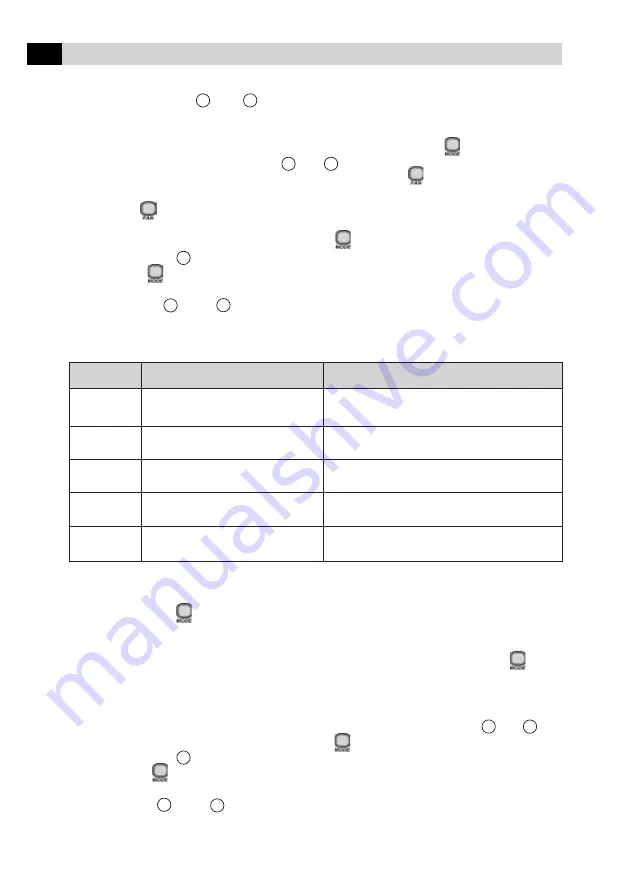
Items 20-24 of the Unit Configuration are available at this point.

Item

Value

Description

20

1. Heatpump

Configuration of the unit

0. Only A/C

Use as default Heat/Cool

21

1-199 in increments of 1

CNN address of the unit

Use as default 1

22

0-199 in increments of 1

Zone Number

Use as default 1

23

1-199 in increments of 1

GFD number

Use as default 1

24

0: Start-up in Off mode

Automatic Reset

1: Start from last mode

Use as default “On”

Entering an installer configuration:

Keep the button       pressed down for 5 seconds, while the CRC is in Off mode. After 5
seconds, a “10” appears; this shows that the user is setting the first item in the software
configuration.

To check the value of the configuration item “10”, press the button    . The
remote configuration value of the Heat/Cool versus Cool is displayed together
with the icon “SET TEMP” to indicate that the number displayed refers to the
configuration data.

To change the remote configuration Heat/Cool versus Cool, use the keys      and      .

To switch to the next setting, press the button       again and “10” is displayed.

Press the button      and the display changes to “11”.

The button     will toggles the display between the software configuration index
(i.e. “10”, “11”, etc.) and the configuration value.

The button      and      change the index or value, i.e. whichever is currently
being displayed.

<

<

<

<

<

<

<

<

<

<

<

<

Summary of Contents for 42XQ Series

Page 1: ...AND START UP INSTRUCTIONS UNDERCEILING CONSOLE FAN COIL UNIT 42XQ XQA 50 60Hz Carrier International Sdn Bhd Malaysia 42XQ 42XQA MODEL W mm D mm H mm Weight kg 42XQ XQA 020 004 23 42XQ XQA 025 006 102...

Page 2: ...2 Electrical Box 42XQ 16 7 3 Changing the Wireless Remote Control to a Wired Remote Control 17 7 4 Electrical Diagram for Indoor Unit 220 240V output signal to compressor 20 7 5 Electrical Diagram for...

Page 3: ...extinguisher periodically to verify that it is completely full and work perfectly Whenever working on the equipment always pay attention to all safety notices written on the labels attached to the uni...

Page 4: ...being exposed to possible work accidents and arrange for their immediate transfer to the place of installation or another safe location When unpacking the units and removing the protective expanded p...

Page 5: ...ded particulate matter which could possibly obstruct the vanes of the outdoor unit It is essential for the indoor unit to posses a hydraulic line to drain off the condensate This hydraulic line must h...

Page 6: ...sewerage systems etc b Install the unit where it is free of any kind of obstruction of the air circulation both in the air intake and the air discharge c Select a location with sufficient space to per...

Page 7: ...4 3 2 PLACEMENT AT THE LOCATION NOTE To fix the indoor unit in place it is necessary to remove its side covers as described in subsection 4 3 3 d Fig 8 indicates the position of the supports Install t...

Page 8: ...s the left side gives access to the electrical box and the electrical connections 4 3 3 REMOVING THE SIDES 1 2 Fig 10 shows the position of the screws to be removed to disassemble the grilles which gi...

Page 9: ...llations on the wall and ceiling and where these pipes must be routed as well as where it is necessary to break the indentation in the right hand side cover of the indoor unit 4 3 5 DRAINING OF THE CO...

Page 10: ...l with a slight inclination towards the drainage side approximately 2o Fig 14 b The unit uses gravity drainage However the drainage pipe must have a downward slope Avoid the situation shown in Fig 15...

Page 11: ...olding charge For more information regarding the additional gas load refer to the table below IMPORTANT Note Model code for Thailand market only Outdoor unit connection for reference only refer to spe...

Page 12: ...condenser The surfacemustbecleanandthemeasurement is performed on the upper part of the pipe to prevent incorrect readings Cover the bulb or sensor with foam to insulate it from the ambient temperatur...

Page 13: ...indicated for the pipes giving consideration to the fact that it is the result of adding the equivalent distances of the pipe curves in a straight line 5 5 Interconnection Junctions The equivalent len...

Page 14: ...st or humidity entering the pipe until it is used Take care to place refrigeration oil on the surfaces in contact between the flanged end and the joint before connecting them together This is done to...

Page 15: ...to the adjacent illustration 6 EXPANSION SYSTEM This system with a piston according to Fig 22 contains a small part with a fixed calibrated orifice which is easily removed on the inside of a nipple fo...

Page 16: ...ith local codes For the cable gauge values of the main power supply presented in the tables the use of copper and or aluminium cables was considered with insulation of the PVC 70o C type and conductor...

Page 17: ...to use the indoor unit from the wireless remote control to the wired remote control the following steps must be followed according to the illustrations on the following pages Disconnect the intermedia...

Page 18: ...18 Fig 25 Changing the remote control use option external connections...

Page 19: ...emote control to connect the threeway cable The terminals are located in the rear part of the cover Insert the cables in the terminals according to the correspondence of the colors Reattach the cover...

Page 20: ...20 Electrical interconnection in the Terminal Plate of the Indoor Unit 42XQ 7 4 Electrical Diagram for Indoor Unit 220 240V output signal to compressor Fig 26 Fig 27...

Page 21: ...21 Electrical interconnection in the Terminal Plate of the Indoor Unit 42XQ 7 5 Electrical Diagram for Indoor Unit 24V output signal to compressor Fig 28 Fig 29...

Page 22: ...22 7 6 Electrical Diagram and Cold Cycle Interconnection Diagram 50Hz Cooling only ELECTRICAL INTERCONNECTION 42XQ XQA 020 025 42XQ XQA 030 42XQ XQA 040 050 060...

Page 23: ...er with respect for the steps described from Section 8 3 onwards 8 CONFIGURING THE SYSTEM 8 1 Changing the Configuration of the Unit from Underceiling to Console The indoor units leave the factory con...

Page 24: ...ss the button to exit the configuration menu To see other available configuration options consult the table 8 3 Configuring the Unit Remote address of indoor unit A Remote address of indoor unit B Def...

Page 25: ...A remote unit A Remote address of indoor unit A b remote unit B Remote address of indoor unit B Ab remote units A and B Default address of the two units tU C degree Celsius Temperature F degree Fahre...

Page 26: ...tem Value Description 20 1 Heatpump Configuration of the unit 0 Only A C Use as default Heat Cool 21 1 199 in increments of 1 CNN address of the unit Use as default 1 22 0 199 in increments of 1 Zone...

Page 27: ...d temperature setpoint is automatically readjusted to the default startup values of 22o C for C mode and 72o F for F mode whenever this configuration item is modified Item Value Description 10 H Remot...

Page 28: ...ed the last value displayed is the new deflector setting for the system The only way to abort a deflector change is to change the value back to its original value ATTENTION NOTE Selecting DEFLECTOR mo...

Page 29: ...tion item CH remote address and the temperature digits show the default value of the respective configuration item Ab control of both indoor units Press the buttons or to change the default value Ab t...

Page 30: ...ion If the sensor temperature of the indoor unit coil does not fluctuate within the range 2o C during the compressor cycle period of 5 minutes the control triggers this error 10 EEPROM error in circui...

Page 31: ...the electrical connections are securely connected Check that there are no leaks of refrigerant Confirm that the force discharge is compatible with the electrical specifications of the unit Ensure that...

Page 32: ...TO OUTDOOR COMPRESSOR Carrier International Sdn Bhd 3385 T Lot 4 Jalan P 6 43650 Bandar Baru Bangi Selangor Malaysia Tel 03 8925 8001 Fax 03 8925 3578 REV 2 42XQ 06 2006 Parent Pt No 42XQ 402 001 IOM...

Reviews: