background image

50

Failure to provide proper water quality will void the fan

coils unit's warranty.

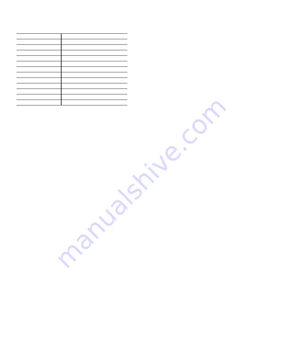
Table 6 — Water Quality Concentrations

Controls Operation — 

Before proper control operation

can be verified, all other systems must be operating properly.

The correct water and air temperatures must be present for the

control function being tested. Some controls and features are

designed to not operate under certain conditions. For example,

on a two-pipe cooling/heating system with auxiliary electric

heat, the electric heater cannot be energized with hot water in

the system. 

A wide range of controls, electrical options and accessories

may be used with the equipment covered in this manual. Con-

sult the approved unit submittals, order acknowledgments, and

other literature for detailed information regarding each individ-

ual unit and its controls. Since controls and features may vary

from one unit to another, care should be taken to identify the

controls used on each unit and their proper control sequence.

Information provided by component manufacturers regarding

installation, operation, and maintenance of their individual con-

trols is available upon request. 

When changing from one mode to another (cooling to heat-

ing or heating to cooling), it may take some time to actually no-

tice a change in the leaving air temperature. In addition, some

units may be designed for a very low air temperature rise in

heating. Before declaring a unit inoperative or a component

defective, it may be necessary to verify operation by more than

one method.

SERVICE

Excessive   Condensation   on   Unit   — 

 Running

chilled water through a fan coil unit with the unit fan off can

cause excessive condensation. If fan cycling is used, a water

flow control valve should be installed to shut off the water

when the fan stops.

Other methods of control that avoid condensation problems

are as follows:

1. Continuous fan operation with motorized chilled water

valve controlled by a thermostat.

2. Continuous fan operation with thermostat control to

switch fan from high to low speed (instead of off).

To Clean Coil

1. Be sure electrical service switch is open, locked, and

tagged while working on unit.

2. Remove return-air grille access panel and brush between

coil fins with stiff wire brush. Care should be taken to not

damage coil fins. Follow-up by cleaning with vacuum

cleaner. If coil is cleaned with air hose and nozzle, take

care not to drive dirt and dust into other components.

Blow air through the coil fins from the leaving air face.

This should again be followed by vacuuming. Units

provided with the proper type of air filters, replaced regu-

larly, will require less frequent coil cleaning.

3. Install clean filter. Refer to Clean or Replace Air Filters

section.

Drain — 

The drain must be checked before initial start-up

and at the beginning of each cooling season to assure that the

drain trap and line are clear. If it is clogged, take steps to clear

the debris so that condensate will flow easily.

Make periodic checks of the drain during the cooling season

to maintain a free flowing condensate. Units provided with sec-

ondary or tell-tale drain connection will indicate a clogged

main line by flow from the tell-tale connection.
NOTE: Should the growth of algae and/or bacteria be a con-

cern, consult an air conditioning and refrigeration supply orga-

nization familiar with local conditions for chemical or other

solution available to control these growths.

Check Drain  — 

Lock open and tag unit electrical service

switch.

Check drain pan, drain line and trap before initial start-up

and at start of each cooling season. A standard type pipe clean-

er for 

3

/

4

-in. ID pipe can be used to ensure that pipe is clear of

obstruction so that condensate is carried away. Check the drain

line at filter cleaning time during the cooling season. Be sure

that debris has not fallen into unit through supply-air grille.

Should the growth of algae and/or bacteria be a concern, con-

sult an air conditioning and refrigeration supply organization

familiar with local conditions for chemicals or other solutions

available to control these agents.

Fan Motor Bearings — 

Lock open and tag unit electri-

cal service switch.

Standard motors are permanently sealed and lubricated. No

lubrication is required unless special motors have been

supplied or unusual operating conditions exist.

Clean Fan Wheel — 

Lock open and tag unit electrical

service switch.

For access to fan assembly, remove front or bottom panel.

Fan assembly may be removed from its tracks if unit has a long

conduit lead. Dirt and debris should not be allowed to accumu-

late on the blower wheel or housing.  This can result in an un-

balanced blower wheel condition which can damage a blower

wheel or motor.  The wheel and housing may be cleaned peri-

odically using a vacuum cleaner and a brush, taking care not to

dislodge the factory balancing weights on the blower wheel

blades.

Clean Electric Heater — 

Lock open and tag unit elec-

trical service switch.

1. Remove dust, dirt, or foreign material before start-up. Do

not block normal airflow to and from units; blockage may

damage electric heaters.

2. Clean heater elements with soft brush or vacuum cleaner

as necessary.

3. To replace blown fusible links (nichrome heaters only):

a. Remove fan deck (horizontal units only) for

access to heater.

b. Remove nut securing link at each end; install new

link; reinstall nuts.

c. Reinstall fan deck (if removed).

Electric resistance heaters typically require no normal

periodic maintenance when unit air filters are changed

properly. The operation and service life may be affected by

other conditions and equipment in the system. The two most

important operating conditions for an electric heater are proper

airflow and proper supply voltage. High supply voltage and/or

poorly distributed or insufficient airflow over the element will

WATER CONTAINING

REQUIRED CONCENTRATION

Sulphate

Less than 200 ppm

pH

7.0 to 8.5

Chlorides

Less than 200 ppm

Nitrate

Less than 100 ppm

Iron

Less than 4.5 mg/l

Ammonia

Less than 2.0 mg/l

Manganese

Less than 0.1 mg/l

Dissolved Solids

Less than 1000 mg/l

CaCO3 Hardness

300 to 500 ppm

CaCO3 Alkalinity

300 to 500 ppm

Particulate Quantity

Less than 10 ppm

Particulate Size

800 micron max

Summary of Contents for 42VA Series

Page 1: ...equipment location such as a ceiling or elevated structure Only trained qualified installers and service mechanics should install and service this equipment When installing this unit observe precauti...

Page 2: ...n return air plenum UNIT SIZE 42C 02 03 04 06 08 10 12 NOMINAL AIRFLOW cfm 200 300 400 600 800 1000 1200 SHIPPING WEIGHT lb 42CA 36 39 49 59 64 95 107 42CE 55 60 70 82 95 135 154 42CG 98 118 126 168 1...

Page 3: ...in Coil Outlet and Inlet 5 8 OD Drain Connection 3 4 MPT UNIT SIZE 42D 06 08 10 12 14 16 18 20 NOMINAL AIRFLOW cfm 600 800 1000 1200 1400 1600 1800 2000 SHIPPING WEIGHT lb 42DA 64 79 90 108 119 124 1...

Page 4: ...robust materials and presents a rugged appearance Still great care must be taken to assure that no force or pressure is applied to the coil piping or drain stub outs during handling Depending on the...

Page 5: ...0 211 4 311 4 16 13 181 4 61 4 83 4 193 4 1 1 0 83 36 03 300 251 4 361 4 20 14 221 4 61 4 83 4 233 4 1 1 1 08 39 04 400 311 4 431 4 26 15 281 4 61 4 83 4 293 4 2 1 1 35 49 06 600 361 4 431 4 31 10 331...

Page 6: ...rall unit dimension increases by 4 in with optional electric heat 5 Not shown 3 speed fan switch wall plate closed cell foam on main drain pan 6 Units have galvanized finish 7 For optional coil connec...

Page 7: ...nn 7 8 in OD 5 Tell Tale Drain Conn 5 8 in OD optional 6 Drip Lip optional shipped loose 7 Filter 8 Return Duct Collar 1 in 9 Filter Access Panel 10 Access Panel 11 Supply Duct Collar 1 in 12 Air Vent...

Page 8: ...5 Drain Conn 7 8 in OD 6 Strip Heater High Limit 7 Tell Tale Drain Conn 5 8 in OD optional 8 Drip Lip optional shipped loose 9 Filter 10 Return Duct Collar 1 in 11 Filter Access Panel 12 Access Panel...

Page 9: ...16 34 53 4 11 1 1 0 83 98 03 300 42 211 2 101 4 38 53 4 11 1 1 1 08 118 04 400 48 257 8 111 16 44 53 4 11 2 1 1 35 126 06 600 53 345 8 93 16 49 63 4 12 2 1 1 88 168 08 800 60 39 101 2 56 63 4 12 2 1...

Page 10: ...0 and 12 have 2 motors 4 blowers 3 Cabinet has an Arctic White baked finish 4 Refer to supply and return connections above for coil stub out locations 5 Not shown 3 speed fan switch wall plate 1 2 in...

Page 11: ...163 4 77 72 7 4 2 10 x 541 2 227 12 1200 75 60 83 4 77 72 7 4 2 10 x 63 241 LEGEND 1 Junction Box 2 L shape Drip Lip optional shipped loose 3 Chilled Hot Water Supply and Return Connection 4 Resilien...

Page 12: ...wer Motor 02 200 35 16 123 4 37 32 6 1 1 10 x 231 2 117 03 300 35 20 83 4 37 32 6 1 1 10 x 28 122 04 400 41 26 83 4 43 38 6 2 1 10 x 321 2 137 06 600 53 31 153 4 55 50 7 2 1 10 x 37 152 08 800 53 38 8...

Page 13: ...227 12 1200 75 60 83 4 77 72 7 4 2 7 x 52 241 a42 4151 NOTES 1 Right hand unit shown left hand unit opposite 2 Internal factory valve package and drains may not align with cabinet knockouts 3 Dimensio...

Page 14: ...123 4 37 32 6 1 1 7 x 21 117 03 300 35 20 83 4 37 32 6 1 1 7 x 21 122 04 400 41 26 83 4 43 38 6 2 1 7 x 27 137 06 600 53 31 153 4 55 50 7 2 1 7 x 38 152 08 800 53 38 83 4 55 50 7 2 1 7 x 38 157 10 10...

Page 15: ...D E Blower Motor 02 200 35 37 32 1 1 0 83 115 03 300 35 37 32 1 1 1 08 120 04 400 41 43 38 2 1 1 35 135 06 600 53 55 50 2 1 1 88 150 08 800 53 55 50 2 1 2 31 155 10 1000 75 77 72 4 2 3 16 227 12 1200...

Page 16: ...hrough 08 have one motor 2 blowers sizes 10 and 12 have 2 motors 4 blowers 3 Bottom access panel has an Arctic White baked finish 4 Refer to supply and return connections above for coil stub out locat...

Page 17: ...SIZE DIMENSIONS in QTY UNIT UNIT WEIGHT lb A B C D Blower Motor 02 243 16 22 23 16 1 1 42 03 243 16 22 23 18 1 1 47 04 343 16 32 33 26 2 1 57 06 443 16 42 43 36 2 1 77 08 463 16 44 45 38 2 1 79 10 603...

Page 18: ...nts UNIT SIZE DIMENSIONS in QTY UNIT UNIT WEIGHT lb A B C D Blower Motor 02 243 16 22 23 16 1 1 42 03 243 16 22 23 18 1 1 47 04 343 16 32 33 26 2 1 57 06 443 16 42 43 36 2 1 77 08 463 16 44 45 38 2 1...

Page 19: ...MENSIONS in QTY UNIT UNIT WEIGHT lb A B C D E Blower Motor 02 41 22 23 171 4 31 8 1 1 63 03 41 22 23 171 4 31 8 1 1 68 04 51 32 33 26 33 4 2 1 82 06 61 42 43 39 21 4 2 1 99 08 63 44 45 39 31 4 2 1 101...

Page 20: ...ts UNIT SIZE DIMENSIONS in QTY UNIT UNIT WEIGHT lb A B C D E Blower Motor 02 41 22 23 171 4 31 8 1 1 63 03 41 22 23 171 4 31 8 1 1 68 04 51 32 33 26 33 4 2 1 82 06 61 42 43 39 21 4 2 1 99 08 63 44 45...

Page 21: ...NSIONS in QTY UNIT UNIT WEIGHT lb A B C D E Blower Motor 02 41 22 23 171 4 31 8 1 1 64 03 41 22 23 171 4 31 8 1 1 69 04 51 32 33 26 33 4 2 1 83 06 61 42 43 39 21 4 2 1 100 08 63 44 45 39 31 4 2 1 102...

Page 22: ...SIZE DIMENSIONS in QTY UNIT UNIT WEIGHT lb A B C D E Blower Motor 02 41 22 23 171 4 31 8 1 1 64 03 41 22 23 171 4 31 8 1 1 69 04 51 32 33 26 33 4 2 1 83 06 61 42 43 39 21 4 2 1 100 08 63 44 45 39 31...

Page 23: ...60 04 400 36 35 30 2 1 2 08 72 06 600 50 49 44 4 2 3 06 110 NOTES 1 Right hand unit shown left hand unit opposite Coil connection locations are 5 8 inch 2 Unit sizes 02 through 04 have one motor 2 bl...

Page 24: ...1 18 50 03 300 28 27 22 2 1 1 53 60 04 400 36 35 30 2 1 2 08 72 06 600 50 49 44 4 2 3 06 110 NOTES 1 Right hand unit shown left hand unit opposite Coil connection locations are 5 8 inch 2 Unit sizes...

Page 25: ...lter 8 Air Vent 1 8 in MPT 9 Optional Valve Package inside cabinet 10 Drain Pan Auxiliary with 3 4 in MPT Drain Connection 11 Return Air Grille NOTES 1 Right hand unit shown left hand unit opposite Co...

Page 26: ...ille 7 Filter 8 Air Vent 1 8 in MPT 9 Front Panel Fastener 10 Optional Valve Package inside cabinet 11 Drain Pan Auxiliary with 3 4 in MPT Drain Connection 12 Return Air Grille NOTES 1 Right hand unit...

Page 27: ...Unit size 01 has one motor one blower size 03 has 2 motors 2 blowers 5 Unit has 1 2 in flanges for mounting to wall surface 6 Front panel hooks at top of unit swing down and snap in at bottom against...

Page 28: ...Motor Junction Box 2 Motor Blower Assembly 3 Electric Strip Heater Element optional 4 Auxiliary Drip Lip optional shipped loose 5 Tell Tale Drain optional 6 Drain Connection 7 8 in OD 7 Air Vent 1 8 i...

Page 29: ...turn Air Plenum 3 Mounting Clips shipped loose 4 Electrical Strip Heater Element optional 5 Auxiliary Drip Lip shipped loose with 3 8 in Hole 6 Tell Tale Drain optional 7 Drain Connection 7 8 in OD 8...

Page 30: ...A42 4122 NOTES 1 Right hand unit shown left hand unit opposite Coil connection locations are 5 8 inch 2 Standard 4 row coil shown Other coil option dimensional data available on request 3 Sizes 06 08...

Page 31: ...Side Access Panels 5 Electrical Strip Heater Element optional 6 Supply Air Duct Connection 1 in 7 Manual Air Vent 8 Filter Throwaway 1 in 9 Return Air Duct Connection 21 2 in 10 Drain 7 8 in OD 11 Bot...

Page 32: ...ary Drip Lip 5 Electric Strip Heater Element optional 6 Coil Inlet Copper Sweat Connection 7 Coil Outlet Copper Sweat Connection 8 Manual Air Vent 9 Filter Throwaway 10 Bottom Access Panel 11 Drain 7...

Page 33: ...ulation service clearances piping and electrical connections and any necessary ductwork For specific unit dimensions refer to Fig 13 23 Allow clearances according to local and national electric codes...

Page 34: ...and 42DC with bottom inlet may be installed in noncombustible return spaces only 5 Mounting units on the floor a Ensure wall behind the unit is smooth and plumb if necessary install furring strips on...

Page 35: ...drain pan or drip lip This helps minimize field piping insula tion requirements Refer to Fig 34 37 for pipe connection configurations NOTE Chilled water piping determines the hand of the unit Fig 31...

Page 36: ...depending on number of coil rows on factory supplied coil or arrangement of factory supplied valves 42VG 42VG a42 4177 HYDRONIC COIL ARRANGEMENT VERTICAL FLOOR UNITS 42VB VE VF Pipe into cabinet end c...

Page 37: ...package to be used for balancing water flow through the coil When isolation valve ball valve or ball valve with memory stop at position H is used for water flow balancing do not specify additional bal...

Page 38: ...4174 a42 4308 Fig 35 Two Way Motorized Control Valve Package with Aquastat Bleed Bypass Line The 2 way motorized valve motor drives valve open and a spring returns valve to normally closed position no...

Page 39: ...n 3 4 in etc 2 PIPE SYSTEM One Valve Package or 4 PIPE SYSTEM Two Valve Packages Application 2 Pipe Hydronic Heating Only 2 Pipe Hydronic Cooling Only 2 Pipe Hydronic Cooling with Total Electric Heat...

Page 40: ...Valve Package without Motorized Control When isolation valves only are specified they will be brazed to the coil stub outs Check job specifications for system pressure pressure drop limitations and fl...

Page 41: ...evation to ensure continu ous condensate removal Proper steam trap selection and installation is necessary As a guideline in creating a steam trap locate the steam trap dis charge at least 12 in below...

Page 42: ...N A 125 240 NO SWAGE Copper tube end expanded to accept a copper tube of the same size for factory or field brazing Application Used where possible for all tub ing joints for best joint integrity N A...

Page 43: ...system water during normal sys tem operation Should not be used in lieu of main system strainers Strainer screen may have to be removed during initial high pres sure system flushing during start up S...

Page 44: ...way motorized valve except with manual override lever engaged the valve is open to both ports and water flow will take the path of least resistance through the valve pack age not necessarily 100 thro...

Page 45: ...4 0 300 200 N A MODULATING VALVE Requires ETO Spring Return Modulating valves are designed to control the flow in the circuit by making incremental adjustments to the flow path within the valve Appli...

Page 46: ...sed to provide automatic summer or winter changeover for the system When a two pipe cooling heating system with optional auxiliary electric heat is desired an additional aquastat is required Units wit...

Page 47: ...ithout intended ductwork attached Units provided with outside air should have some method of low temperature protection to prevent freeze up This pro tection may be any of several methods such as a lo...

Page 48: ...after start up operations When steady stream of water begins to escape close valve Vent release air slow ly usually dripping water into drain pan in the process Make sure all service valves are open a...

Page 49: ...See Fig 42 and 43 Air System Balancing All duct stubs grilles filters and return access panels must be properly installed to establish actual system operating conditions BEFORE beginning air bal ancin...

Page 50: ...the cooling season to maintain a free flowing condensate Units provided with sec ondary or tell tale drain connection will indicate a clogged main line by flow from the tell tale connection NOTE Shoul...

Page 51: ...ter of the size shown in Tables 1 4 Do not attempt to clean and reuse disposable filters If the replace ment filters are not purchased from the factory the filters used should be the same type and siz...

Page 52: ...otentiometer and to the left of the orange relay 5 Attach the red positive lead of the meter to the red wire that bridges the 0 10 vdc outputs high medium and low 6 High Speed Close high speed relay b...

Page 53: ...below the status light 5 Attach the red positive lead of the meter to the high speed Flo1 terminal below the potentiometer 6 High Speed Using a small screwdriver turn the Flo1 po tentiometer so the m...

Page 54: ...rsion Typ ical 42CEA03 Rear Return Unit Shown in Pic tures Below 1 Remove filter and access panel 2 Install access panel on the rear of the unit with 5 screws 3 Bend the tabs on each of the plenum sid...

Page 55: ...3 Remove access panel 4 Install access panel on the rear of the unit 5 Install duct collar assembly 6 Slide the filter in the duct collar opening and install filter bracket Conversion is complete To...

Page 56: ......

Page 57: ......

Page 58: ...right to discontinue or change at any time specifications or designs without notice and without incurring obligations Catalog No 04 53420011 01 Printed in U S A Form 42 6SI Pg 58 11 17 Replaces 42 5SI...

Page 59: ...an rotation 7 Unit mounted level and square 39 Record electrical supply voltage 8 Proper access provided for unit and accessories 40 Record ambient temperatures 9 Proper electrical service provided 41...

Page 60: ..._________________________________________________________ ______________________________________________________________________________________________________________________________________________...

Reviews: