


6
Individual Unit Operation
POWER A UNIT ON OR OFF — To power an individual
unit on or off, use the arrow buttons to navigate to the unit in
the address grid. Press the Power button one short press to turn
the unit on (if it is off) or off (if it is on).
CHANGE SETTINGS FOR A UNIT
1.
Use the arrow buttons to navigate to the unit in the ad-
dress grid.
2.
Press SET.
3.
Use the MODE, FAN, INC, and DEC buttons to set the
operation mode and parameters such as setpoint and fan
speed. (See the Control Summary section below for
details.)
4.
Press OK to transmit all current settings to the selected in-
door unit.
Global Operation
POWER ALL UNITS OFF OR ON
• Press the Power button one short press to power off all
units currently operating.
• If all indoor units are off, press the Power button one
short press to power on all units to the currently selected
parameters, such as mode, fan speed, and setpoint.
• Press the Power button one long press to send all com-
mands to all indoor units, whether the unit is currently
powered on or off. All indoor units currently off will be
powered on, and all units will receive the commands.
CHANGE SETTINGS FOR ALL UNITS
1.
Press SET to select all of the indoor units.
2.
Use the MODE, FAN, INC, and DEC buttons to set the
operation mode and parameters such as setpoint and fan
speed. (See the Control Summary section below for
details.)
3.
Press OK to transmit all current settings to all units.
Control Summary —
Refer to Fig. 7 for the locations of
the buttons described below.
POWER — Press to turn the selected indoor units on or off.
See the sections Individual Unit Operation and Global Opera-
tion above.
OK — While in Settings mode (see below), press OK to send
all active and updated commands to the selected indoor units.
SET — Press the SET button to enter Settings mode and to
toggle between an individual unit setting or a global setting for
all indoor units. (The default is a single indoor unit.) The set-
tings of the first connected indoor unit are displayed. See
Fig. 10 for an example of a Settings mode display screen.
TIME ON/TIME OFF — While in Settings mode (see
above), press TIME ON to set up the delayed operation start
time for the selected indoor units. Press the INC button to se-
lect the start hour from 0 to 24 hours. Each button press incre-
ments the setting by
1
/
2
hour for the first 10 hours, then by 1
hour. When the start time is correct, press TIME ON again to
set the start time. Press TIME OFF to set the delayed operation
stop time, use the INC button to set the time, and press TIME
OFF again to set the selected time. Press TIME OFF again to
exit timer mode and return to normal operation.
MODE — While in Settings mode (see above), press MODE
to set the operation mode for a single indoor unit or globally for
all connected indoor units. Each MODE press toggles to the
next operating mode selection.
FAN — While in Settings mode (see above), press FAN to set
the fan speed of the selected indoor unit (Auto
Low
Me-
dium
High).
SWING — While in Settings mode (see above), press SWING
to enable or disable louver settings for the selected indoor units
(function not available on all units).
INC/DEC (TEMPERATURE SETPOINT) — While in Set-
tings mode (see above), press INC (increase) to increase the
temperature setpoint by 1 degree. Press DEC (decrease) to de-
crease the temperature setpoint by 1 degree.
QUERY — Press to display the operation status of a selected
indoor unit. The display defaults to the first connected indoor
unit. Use the right and left arrow buttons to navigate between
indoor units. Press and hold the right or left arrow button to
scroll through the connected units in the address grid. Use the
INC and DEC buttons to move to the next or previous row of
indoor units in the grid. See Fig. 11 for an example of a Query
mode display screen.
From the Main screen, pressing the up, down, right, or left
arrow button also activates Query mode.
IMPORTANT:
Frequent changes to operating mode
may cause the system to malfunction. Allow at least
one minute between mode changes to allow the system
to stabilize.
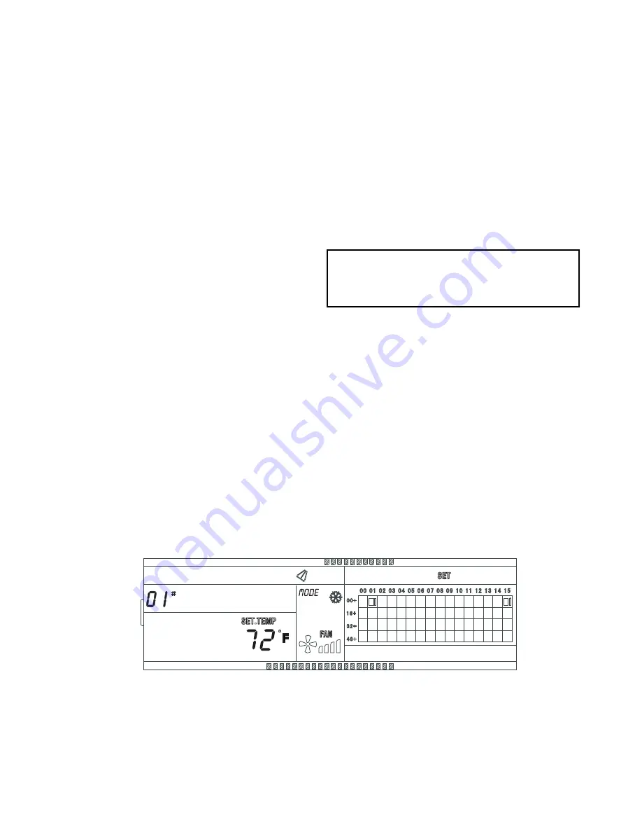
a40-1887
Fig. 10 — Settings Mode Display Screen (Example)
In this example:
1. The indoor unit with the address 01 is selected.
2. The unit is in Cooling mode, the fan speed is High, Swing mode is on,
and the set point is 72 F.
3. In the address grid, only the large and small blocks at addresses
00+,01 and 00+,15 are lit. This means only the indoor units with the
addresses of 01 and 15 are connected and powered on.


