


8
INSTALLATION LOCATION REQUIREMENTS
Indoor Unit
S
Confirm that the ceiling is able to support the weight of the unit.
S
There should be enough room within the false ceiling for
installation and maintenance.
S
The false ceiling should be horizontal and leveled.
S
Install the unit in a location within the room that allows uniform
air flow in all directions.
S
Do not install the indoor units near a direct source of heat such as
direct sunlight or a heating appliance.
S
A location which provides appropriate clearances.
S
Ensure the hanger is strong enough to withstand the unit’s weight.
Indoor and Outdoor Units (General)
S
Ensure space is left for access for maintenance.
S
Location should be far away from where there is a heat source,
leakage of any inflammable, explosive substances, or smog.
S
All wiring and refrigerant lines must be at least 3 ft. (1m) away
from sources of electromagnetic interference (televisions, radios,
etc.). Interference is still possible even if this distance is maintained.
S
Do not install the indoor or outdoor units in a location with
special environmental conditions. For those applications, contact
your Ductless representative.
INDOOR UNIT INSTALLATION
INDOOR DUCTED UNIT INSTALLATION
!
Be sure that the ceiling grid is supported separately from
the unit.
The ceiling grid must not be supported by any part of the
unit or any associated wiring or piping work.
CAUTION
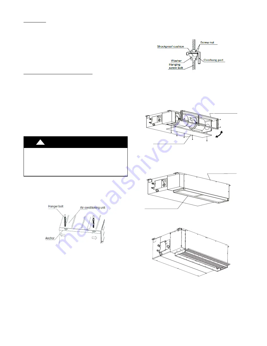
MOUNTING THE UNIT
1. INSTALLING HANGER BOLTS − Install the hanger bolts
at the locations (see Fig. 8, top view). Use a Ø0.39in.
/(10mm) all−threaded rod.
Fig. 8 −
Install the Hanger Bolts
2. The unit can now be lifted on to the hanging rods for
mounting.
3. Use rods and fasteners to suspend the unit at the factory
provided mounting holes.
4. Adjust the unit’s height until the bottom is level with the false
ceiling, with adequate space to provide enough pitch for the
drain.
5. Secure the unit in position with lock nuts and washers on
both sides of the mounting bracket. Ensure the threaded
rod does not extend more than 2 in. below the mounting
brackets (see Fig. 9).
A150665
Fig. 9 −
Secure the Unit
RETURN AIR ARRANGEMENT (ONLY SIZES 09−48)
Based on the return air arrangement requirement in the field, the
unit can be modified from the rear return to the bottom return.
1. Remove the return Air Return Flange/filter rack and plenum
bottom panel.
Air return flange
Ventilation panel
Fig. 10 −
Remove the Return Air Return Flange
2. Install the Seal Sponge on the bottom inlet.
3. Swap the position to change the rear return to bottom return
arrangement installing the Air Return flange and the filters.
Air return flange
Ventilation panel
Fig. 11 −
Change the Rear Return
4. Install the filter brackets to lock the filter in place.
Fig. 12 −
Install the Filter Brackets
Summary of Contents for 40MBDQ series
Page 6: ...6 DIMENSIONS CONT Airflow Airflow Fig 5 Indoor Unit Sizes 58K...
Page 14: ...14 FAN PERFORMANCES AT VARYING STATIC PRESSURES CONT Fig 32 Fan Performance 40MBDQ09...
Page 15: ...15 FAN PERFORMANCES AT VARYING STATIC PRESSURES CONT Fig 33 Fan Performance 40MBDQ12...
Page 16: ...16 FAN PERFORMANCES AT VARYING STATIC PRESSURES CONT Fig 34 Fan Performance 40MBDQ18...
Page 17: ...17 FAN PERFORMANCES AT VARYING STATIC PRESSURES CONT Fig 35 Fan Performance 40MBDQ24...
Page 18: ...18 FAN PERFORMANCES AT VARYING STATIC PRESSURES CONT Fig 36 Fan Performance 40MBDQ36...
Page 19: ...19 FAN PERFORMANCES AT VARYING STATIC PRESSURES CONT Fig 37 Fan Performance 40MBDQ48...
Page 20: ...20 FAN PERFORMANCES AT VARYING STATIC PRESSURES CONT Fig 38 Fan Performance 40MBDQ58...


