background image

Piping Connections / Piping 

Refer to Physical Data Table for correct piping sizes. The length of refrigerant pipe depends on the unit 
placement and building structure – attempt to run pipes as 

1.  Refrigerant tubing between sections may be made using accessory tubing packages or field-supplied 

tubing of refrigerant grade, correct size and condition. 

2.  Refrigerant suction tube must be insulated with closed-cell foam type insulation with a minimum wall 

thickness of 3/8 in. Failure to properly insulate refrigerant tubes adequately will degrade system 
performance and efficiency as well as permitting moisture or frost to form on the tubing surfaces during 
operation. 

3.  Run refrigerant tubes as directly as possible, avoiding unnecessary turns and bends. 
4.  If tube bending is necessary, use only copper cutter to cut the copper tube and shape tube with a tube 

bender so that the tube ends coincide with flare connections. 

5.  Carefully remove the flare nut fitting from indoor and outdoor sections tubing. 
6.  Thoroughly clean all tubing connection points to prevent foreign matter from entering the refrigerant 

circuit. 

7.  Thread the 2 fittings by  hand, making sure the threads fit smoothly and the flare seats evenly against the 

union. 

8.  Tighten the 2 fittings securely. 
9.  Connect piping to the indoor and outdoor section. 
10. Evacuate the system at lower 500-micron for at least 30 minutes. 
11. Suspend refrigerant tubes so they do not damage insulation on liquid and vapor tubes and do not 

transmit vibration to structure. Also, when passing refrigerant tubes through walls, seal opening so 
vibration is not transmitted to structure. Leave some slack in refrigerant tubes between structure and units 
to absorb vibration. 

12. After evacuating the system, turn on both valves at the condensing unit to flow the refrigerant into the 

system. Outdoor unit contains holding refrigerant charge to operate split system. 


- 6 -


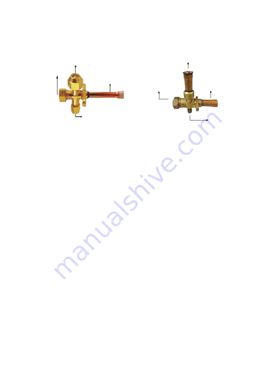
Service Valve (Blazing)

Service Valve (Flare)

CONNECTION TO
INDOOR PIPING (Brazing)

SERVICE PORT
(SCHRAEDER)

FACTORY-BRAZED
TO CONDENSING UNIT

SHUT-OFF PORT

CONNECTION TO

INDOOR PIPING (Flare)

FACTORY-BRAZED

TO CONDENSING UNIT

SERVICE PORT

(SCHRAEDER)

SHUT-OFF PORT

Summary of Contents for 38LB007SC

Page 1: ... UP AND SERVICE INSTRUCTIONS 38LB 38LF AIR COOLED CONDENSING UNIT CONTENTS PAGE PHYSICAL DATA 2 PHYSICAL DATA 2 DIMENSION DATA 3 RIGGING UNPACKING 4 CONFIGURATION 5 ELECTRICAL DATA 5 PIPING CONNECTIONS PIPING 6 MAINTENANCE 7 WIRING DIAGRAM 8 9 ATTENTION BEFORE OPERATING 10 1 ...

Page 2: ...1050 Depth mm 725 915 1080 1190 Weight kg 97 100 193 209 245 294 1 1 8 Brazing Dimension Compressor Description Nominal Cooling Capacity Fan Motor Safety Device Refrigerant Piping Connections 38LB 38LF 38LF048 38LF060 38LF007 38LF009 38LF012 38LF015 Btu hr 48 000 60 000 78 000 98 000 120 000 150 000 w 14 1 17 6 22 9 28 7 28 7 44 0 Power Consumption w 4 470 5 380 6 270 9 320 10 880 14 380 Power Sup...

Page 3: ...38LB 38LF Dimension mm Dimension mm 3 Dimension Data ...

Page 4: ...cessary x Confirm the nameplate voltage to ensure that it matches available power supply x Consult building and electrical codes as required in your area Location Unit should be installed outdoors Do not restrict service wiring and piping areas Also avoid positioning unit in manner restriction airflow or in areas where water will pour directly onto unit Minimum recommended clearance space is shown...

Page 5: ...p panel on front of unit and secure with screws 4 Final assembles fan discharge panel Pull fans motor wires taut and retie extra length in control box 5 Check fan for free rotation and observe that wiring has not been damaged or improperly strained 5 Min Max RLA LRA QTY RLA Power Wire mm 2 Ground Wire mm 2 Field CB AT 38LF048 380V 3Ph 50Hz 342 415 7 4 52 0 1 1 49 4 2 5 20 38LF060 380V 3Ph 50Hz 342...

Page 6: ...utdoor sections tubing 6 Thoroughly clean all tubing connection points to prevent foreign matter from entering the refrigerant circuit 7 Thread the 2 fittings by hand making sure the threads fit smoothly and the flare seats evenly against the union 8 Tighten the 2 fittings securely 9 Connect piping to the indoor and outdoor section 10 Evacuate the system at lower 500 micron for at least 30 minutes...

Page 7: ...ordinary hose at a pressure high enough to clean efficiently Coils are double row and may be separated carefully and sufficiently be loosening screws at one end of the coil so that dirt may be flushed out towards the outside of both coils Avoid splashing mud on coil or water onto fan motor Condensing fan adjustment The fan should be adjusted by loosening the set screws and moving the fan blade up ...

Page 8: ... 38LB036SCG 040SCG 048SC 060SC Å o µ 380 ê r ª Å o µ ε n 38LB007SC 009SC 009SC D 012SC 012SC D Å o µ 380 ê r 38LB 048SC 060SC 38LF 048 060SC 8 Wiring Diagram 38LB 007SC 009SC 009SC D 012SC 012SC D 38LF 007 009 012 ...

Page 9: ... L TB 8 LPS HPS GRN GRD 220V 50Hz AC CONTROL SUPPLY LEGEND COMPONENT ARRANGEMENT COMP COMPRESSOR C CONTACTOR CH CR CRANKCASE HEATER CONTROL RELAY LPS OFMC IP HPS LOW PRESSURE SWITCH OUTDOOR FAN MOTOR INTERNAL PROTECTOR HIGH PRESSURE SWITCH TM OFM CAPACITOR SOLID STATE TIMER OUTDOOR FAN MOTOR FIELD WIRING TERMINALS BLOCK TB CR TM C OFMC 1 2 4 3 8 N L 5 TB 1 2 5 6 3 4 TC RED TC THERMOSTAT CONNECTOR ...

Page 10: ...ding 7 After a long use check the unit fixing for damage 8 Before cleaning be sure to stop the operation and turn off the breaker As the fan is rotating at high speed cleaning during operation may cause injury 9 Do not place a vessel containing water or any object on the condensing unit and do not stand or sit on the condensing unit 10 The condensing unit should not be installed where normal opera...

Reviews: