


13. C
ONTROL
AND
ANALYSIS
OF
BREAKDOWNS
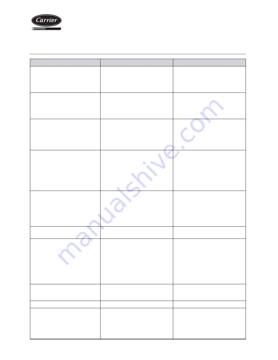
Symptom
Cause
Solution
Evaporation pressure very high in relation with
the air inlet
a) Charge excess
b) High air temperature
c) Compressor suction not air tight
d) Cycle reversing valve in middle position
a) Collect refrigerant
b) Verify overheating
c) Verify compressor state and replace
d) Check that the valve is not clogged. Replace if
necessary
Very low condensation pressure
a) Gas lack
b) Compressor suction not air tight
c) Cycle reversing valve in middle position
d) Liquid circuit plugging
a) Search for leaks, complete charge
b) Verify compressor state and replace
c) Check that the valve is not clogged. Replace if
necessary
d) Verify the dehydrating
fi
lter and expansion valve
Condensation pressure very high in relation to
the air outlet, high pressostat cutoff
a) Insuf
fi
cient air
fl
ow
b) Air inlet temperature very high
c) Dirty condenser (does not exchange)
d) Much refrigerant load (
fl
ooded condenser)
e) The condenser fan is broken down
f) Air in the cooling circuit
a) Verify the air circuits (
fl
ow,
fi
lter cleanliness...)
b) Verify the control thermostat readjustment
c) Clean it
d) Collect refrigerant
e) Repair
f) Make vacuum and load
Evaporation pressure too low (low pressostat
cut-off)
a) Low
fl
ow in evaporator. Air recirculation
b) Frozen evaporator
c) Liquid line as different temperatures at
fi
lter inlet
and outlet
d) Gas lack
e) Very low condensation pressure
f) Evaporator fan broken down
a) Verify the air circuits (
fl
ow,
fi
lter cleanliness...)
b) Verify defrost
c) Replace
fi
lter
d) Search for leaks, complete charge
e) Temperature of air or water in condenser very
low (air or water
fl
ow very high), adjust
fl
ow
f) Repair
Compressor does not start, does not make
noise (humming)
a) No power
b) The contacts of a control element are open
c) Timing of anti cycle short does not allow the
starting
d) Open contact
e) Contactor coil burnt
f) Indoor klixon open
a) Check differential, fuses
b) Verify the safety chain of the electronic control
c) Verify electronic control
d) Replace
e) Replace
f) Wait for reactivation, verify current absorbed
Compressor does not start, motor sounds
intermittently
a) Electrical power supply very low
b) Power cable disconnected
a) Control line voltage and locate voltage drop
b) Verify connections
Repeated compressor starts and stops
a) Because of high pressure
b) Control differential too short (short cycle)
c) Insuf
fi
cient gas, cut-off because of low pressure
d) Dirty or frosted evaporator
e) The evaporator fan does not work, cuts off the
low pressostat
f) Expansion valve damaged or clogged by
impurities (cuts off low pressostat)
g) Dehydrating
fi
lter clogged (cuts off low safety)
a) Verify charge
b) Increase differential
c) Search for leak, reload unit
d) Clean, verify evaporator air circuit
e) Replace or repair
f) Replace, as well as
fi
lter
g) Replace
The compressor makes a noise
a) Loose attachment
b) Oil lack
c) Compressor noise
a) Fix
b) Add oil to recommended level
c) Replace
Noisy operation
a) Unit installed without antivibration protection
a) Place base over shock absorbers
Cycle reversing is not carried out:
- No
defrosting
- Does not change winter - summer cycles
a) Electrical fault
b) Inversion valve coil defective
c) Defrost method not working
d) Cycle reversing valve in middle position
e) Control fault
a) Locate and repair
b) Replace
c) Verify parameters
d) Tap with running compressor. Replace if
necessary
e) Locate and repair
Split-system cooling units
and heat pumps
19


