


Refrigerant
Only quali
fi
ed personnel must perform a periodic tightness control, in
accordance with the regulation (CE)
Nº 517/2014.
- The frequency of checks is no longer related to the load of refrigerant
but to its global warming potential:
Load kg x GWP = t CO2e
Carbon dioxide equivalency (t CO2e ) is a quantity that describes, for
a given mixture and amount of greenhouse gas, the amount in tonnes
of CO2 that would have the same global warming potential (GWP).
Please, consult data of carbon dioxide equivalency (t CO2e) provided
in the technical characteristics tables of this manual.
- Operators shall ensure that the unit is checked for leaks ad minima
according to the following frequency:
• t CO2e < 5 ............ not subjected
• t CO2e 5 to 50 ...... every year
• t CO2e 50 to 500 ... every 6 months
• t CO2e > 500 ......... every 3 months
- Where a leakage detection system has been installed the frequency
of checks is halved.
Note: Never forget that the cooling systems contain liquids and vapours
under pressure. The service pressure of R-410A is approximately 1.5
higher than that of R-407C.
- All necessary precautions must be taken during the partial opening
of the cooling circuit. This opening entails the discharge of a certain
amount of refrigerant to the atmosphere. It is essential to limit this
quantity of lost refrigerant to a minimum by pumping and isolating
the charge in some other part of the circuit.
- The refrigerant
fl
uid at low temperature can cause in
fl
ammatory
injuries similar to burns when contacting the skin or eyes. Always use
safety goggles, gloves, etc. when opening ducts that may contain
liquids.
- The refrigerant in excess must be stored in appropriate containers
and the amount of refrigerant stored at the technical rooms must be
limited.
- Refrigerant barrels and deposits must be handled with precaution
and visible warning signs must be placed to attract attention over
the risks of intoxication,
fi
re and explosion linked to the refrigerant.
- At the end of its useful life, the refrigerant must be retrieved and
recycled as per the current regulations.
Compressor
In the case of compressor replacement:
- Disconnect the unit from power supply.
- Completely empty the load of refrigerant using a speci
fi
c recovery
unit for R-410A
- Disconnect electrically the compresor.
- Carefully unscrew the suction and discharge piping.
- The compressor is
fi
xed onto the platform with 4 screws Ø 8 mm.
Unscrew the
fi
xings.
- Place the new compressor and check that it has a suf
fi
cient oil charge.
Warning: when tightening the compressor screws, please consult
the maximum torque that can be applied.
If a torque wrench is not available, tighten them until noticing
resistance, then tighten the screws by turning them 3/4 of a revolution.
- Screw the suction and discharge piping.
- Connect the compressor in accordance with the circuit diagram.
- Make vacuum and next, reload the gas into the unit according to
load data provided in the technical characteristics table and in the
unit’s data plate.
Liquid sight glass
- This sight glass, located on the liquid line, after the dehydrating
fi
lter, enables controlling the refrigerant load and the presence of
moisture in the circuit. The presence of bubbles in the indicator
means that the refrigerant
fl
uid load is insuf
fi
cient or that there are
non-condensable products in the cooling circuit. The presence of
moisture is characterised by the change in colour of the control paper
located on the sight glass.
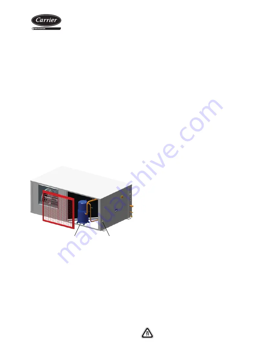
- In the 38HB/HF units the liquid sight glass is located on the support
next to the electric panel.
Warning:
If the unit stops, certain indicators may appear in yellow; the change in
colour is due to the sensitivity, which depends on the temperature of the
fl
uid. These will change to green after a few hours of the unit operating.
If the indicators remain yellow, that will indicate the presence of
excessive humidity in the circuit. This will require the presence of a
specialist.
Compressor
Liquid sight glass
V-220005
Air coil
- Check that the coil is free from dust and grease.
- Cleaning the accumulated dust on the coil can be performed with
a vacuum cleaner perpendicular to the
fi
ns or with a low-pressure
water cleaner. Grease can be removed with water with degreaser.
Do not put stress on the
fi
ns as they could deform.
Use safety gloves for this task. Take care with the sharp
parts of the coil.
Split-system cooling units
and heat pumps
17


