


An oil heater is controlled by the PIC to maintain oil tem-
perature above 140 F (60 C) or refrigerant temperature plus
60° F (15.6° C) (see the Controls section) when the com-
pressor is off. The LID Status02 table displays whether the
heater is energized or not. If the PIC shows that the heater
is energized, but the sump is not heating up, the power to the
oil heater may be off or the oil level may be too low. Check
the oil level, the oil heater contactor voltage, and oil heater
resistance.
The PIC will not permit compressor start-up if the oil tem-
perature is too low. The control will continue with start-up
only after the temperature is within limits.
SCHEDULED MAINTENANCE
Establish a regular maintenance schedule based on the ac-
tual machine requirements such as machine load, run hours,
and water quality. The time intervals listed in this section are
offered as guides to service only.
Service Ontime —
The LID will display a SERVICE
ONTIME value on the Status01 table. This value should be
reset to zero by the service person or the operator each time
major service work is completed so that time between serv-
ice can be viewed.
Inspect the Control Center —
Maintenance is lim-
ited to general cleaning and tightening of connections. Vacuum
the cabinet to eliminate dust build-up. In the event of ma-
chine control malfunctions, refer to the Troubleshooting Guide
section for control checks and adjustments.
Be sure power to the control center is off when
cleaning and tightening connections inside the control
center.
Check Safety and Operating Controls Monthly
—
To ensure machine protection, the Control Test Auto-
mated Test should be done at least once per month. See
Table 3 for safety control settings. See Table 7 for Control
Test functions.
Change Oil and Oil Filters
1. Transfer refrigerant into storage tanks.
2. Turn off oil heater.
3. When machine pressure is 5 psig (35 kPa) or less, drain
the oil reservoir by opening the drain valve (Fig. 2). Open
valve slowly against refrigerant pressure.
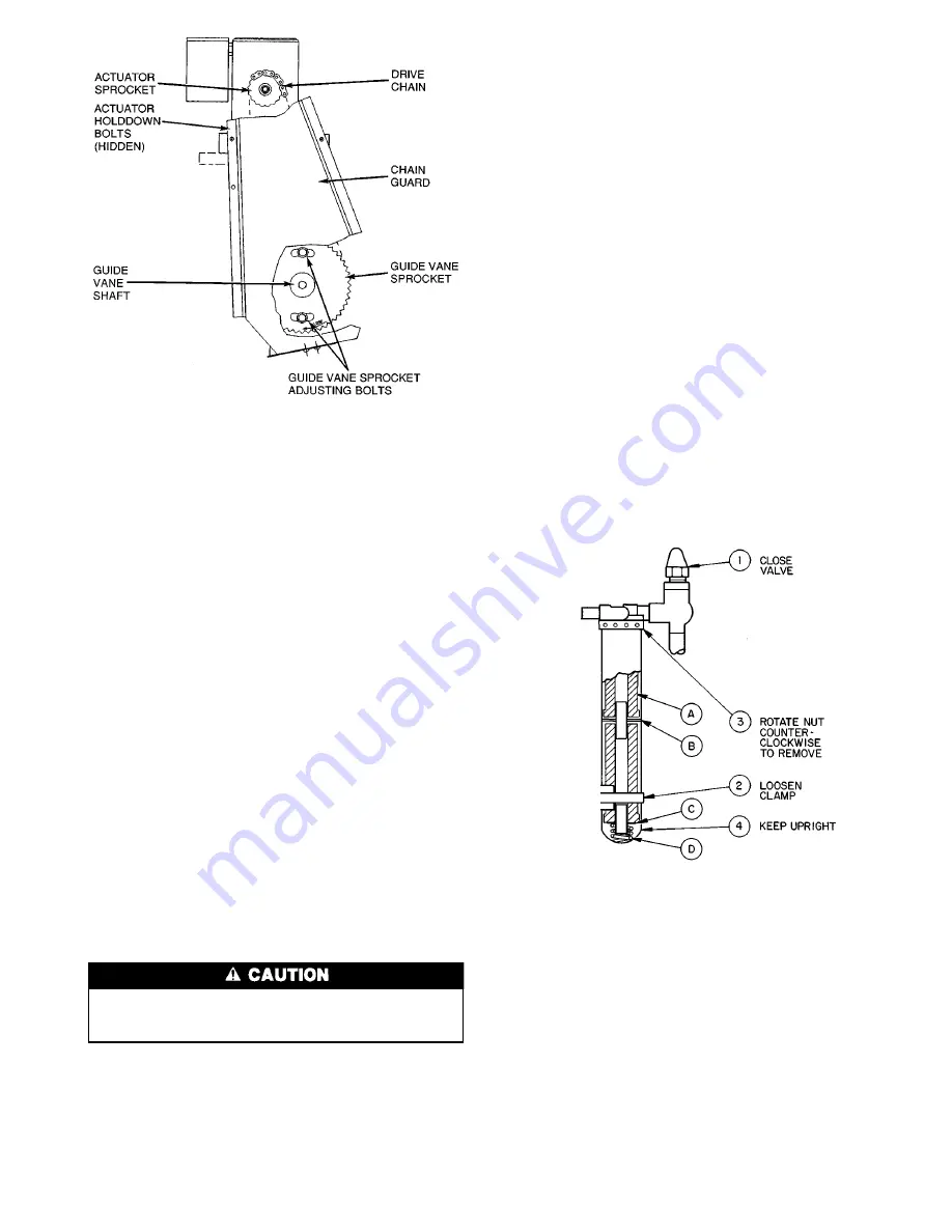
4. Close the line valve (Fig. 29, Item 1) to isolate the oil
filter(s).
5. Loosen the filter holding clamp (Item 2).
6. Rotate filter nut (Item 3) counterclockwise to remove
filter housing. Keep the filter housing upright to avoid
oil spill.
7. Drain the oil; remove and replace filter cartridges. Do
not use any of the extra felt washers supplied with the
filters.
8. Bench assemble Items A-D upside down. Then slide fil-
ter housing over the stack to ensure that spring
(Item D) is centered in the bottom of the filter housing
as indicated.
9. Charge machine with oil. Approximately 15 gal. (57 L)
for 19EF4 size compressor should bring level into com-
pressor sight glass.
10. Turn on oil heater and warm the oil to 140 to 150 F
(60 to 66 C). Operate the oil pump for 2 minutes. Add
oil if required to keep level up to lower sight glass.
Oil should be visible in the reservoir sight glass during
all operating and shutdown conditions.
Oil Specification —
If oil is to be added, it must meet
the following Carrier specifications:
• Oil Type for units using HFC-134a . . . . . . . . . Inhibited
polyolester-based synthetic compressor
oil formatted for use with HFC,
gear-driven, hermetic compressors.
ISO Viscosity Grade . . . . . . . . . . . . . . . . . . . . . . . . . . 68
The polyolester-based oil may be ordered from your local
Carrier representative.
Oil Changes —
Carrier recommends changing the oil
and filter after the first year of operation and every three years
thereafter as a minimum along with a yearly oil analysis.
However, if a continuous oil monitoring system is function-
ing and a yearly oil analysis is performed, time between oil
changes can be extended.
Fig. 28 — Guide Vane Actuator Linkage
Fig. 29 — Removing the Oil Filter
51
Summary of Contents for 19EF Series
Page 10: ...Fig 5 19EF Controls and Sensor Locations cont 10...
Page 13: ...Fig 12 19EF Menu Structure 13...
Page 14: ...Fig 13 19EF Service Menu Structure 14...
Page 38: ...Fig 24 19EF Leak Test Procedures 38...
Page 69: ...Fig 36 Electronic PIC Controls Wiring Schematic 69...
Page 70: ...Fig 36 Electronic PIC Controls Wiring Schematic cont 70...
Page 71: ...Fig 37 Machine Power Panel Starter Assembly and Motor Wiring Schematic 71...


