


1. Correct nozzle size has been selected for desired input rate.
2. Blower wheel support is removed.
3. Electrical wiring is completed according to Fig. 3 or 4.
4. Blower access door is secured in place.
5. Valve on oil supply line is open.
6. RESET BUTTON on primary control is pushed down.
7. Flame observation door is closed.
8. Thermostat is set for heating mode and set above room
temperature.
If all of the above items have been performed, set main electrical
switch to ON position and burner should start. When burner starts,
proceed to Combustion Check section.
Step 2-Combustion Check
In order to obtain optimum performance from oil burner, the
following setup procedures must be followed:
1. A test kit to measure smoke, stack draft, over-fire draft, oil
pump pressure, CO
2
, and stack temperatures MUST be used in
order to obtain proper air band setting. Although all of the
above measurements are required for optimum setup and
efficiency data, the most important readings that must be taken
are smoke number, over-fire draft, stack draft, and pump
pressure.
2. The proper smoke number has been established by engineer-
ing tests to be between 0 and 1. This degree of smoke emission
is commonly referred to as a “trace” of smoke. It is recom-
mended to use a Bacharach true spot smoke test set or
equivalent.
3. In order to ensure proper draft through furnace, a barometric
draft regulator (supplied with furnace) must be installed. In
order for this device to function properly, barometric damper
must be mounted with hinge pins horizontal and face of
damper vertical. (See instructions included with damper.) The
draft regulator should be adjusted after furnace has been firing
for at least 5 minutes, and set between -0.025 and -0.035 in.
wc. (See Table 9.)
4. The over-fire draft, which is taken through observation door
(located in center line above burner in front panel of furnace),
is a measurement necessary to determine if there is a blockage
between oil burner and flue outlet.
There should be a total pressure drop of between 0.020 and
0.05 in. wc through furnace as shown in Table 9. The over-fire
draft must be set within the range shown in Table 9. A reading
outside the range shown in Table 9 (for e0.1 in. wc)
would indicate that furnace is in an extremely high-pressure
condition in primary section. This condition may be caused by
any of the following problems:
a. Excessive combustion air due to air shutter being too wide
open.
b. A lack of flue draft (chimney effect) or some other
blockage, such as soot, in secondary section of heat
exchanger.
c. Use of an oversized nozzle input.
d. Pump pressure over the values listed in Table 10.
5. The CO
2
and stack temperature instruments enable you to
obtain data required to determine thermal efficiency of fur-
nace.
6. An oil filter should be installed as close to burner as possible
with ALL oil burners and is essential on lower firing rate
burners. We recommend the use of a low pressure drop oil
filter such as the General Filter, Inc. model #1A-25A or
equivalent.
7. The oil pressure regulator is factory set to give oil pressure of
130 psig for the model having 105,000 BTUH input and 130
psig for the model having 119,000 BTUH input. The firing
rate noted on nameplate may be obtained using the nozzles
and pump pressures indicated in Table 10.
8. On a new installation, air entrapped in oil line leading from
tank to nozzle must be thoroughly purged in order to prevent
excessive after drip. The oil pump is provided with a special
fitting which allows purging of any air between tank and oil
pump. The proper procedure for performing this operation is
as follows:
a. Place a piece of clear plastic 1/4-in. diameter tubing over
purge fitting on oil pump.
b. Start oil burner, then open purge fitting and allow burner to
run until purge tube is completely free of air bubbles.
c. Tighten purge fitting. Allow oil to run to nozzle and fire
burner.
d. If purging takes longer than 15 sec and no flame has been
established, burner stops. Push reset button on front of
primary control to restart burner.
e. For detailed information on operation of primary control,
refer to instructions included with furnace.
After all the setup procedures mentioned above have been com-
pleted, the burner should be allowed to operate and an inspection
mirror should be used to observe the flame pattern at tip of nozzle.
Any irregularities such as burning to 1 side or pulsating flame
patterns should be corrected by changing nozzle.
Step 3-Fan Adjustment Check
This furnace is equipped with a 4-speed direct-drive motor to
deliver a temperature rise within range specified on rating plate,
between return and supply plenums, at external duct static pressure
noted on rating plate.
When operating furnace in heating mode, static pressure and
temperature rise (supply-air temperature minus return-air
temperature) must be within those limits specified on rating
label. Failure to follow this warning could lead to severe
furnace damage.
Adjust fan speed ACCORDING TO OIL INPUT SELECTED so
that temperature rise is within rise range specified on rating plate.
(See Table 11.) Consult wiring diagram for speed changes on
direct-drive motor.
To adjust fan off time, set DIP switches on control board to obtain
desired timing. (See Fig. 5.)
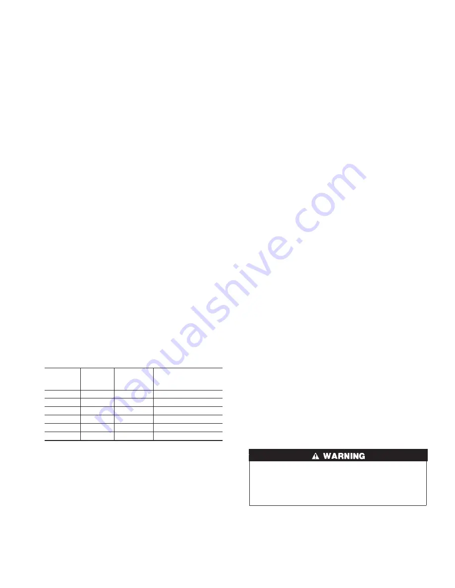
Table 9-Furnace Draft Conditions (In. WC)
FURNACE
INPUT
(BTUH)
FLUE
DRAFT
MINIMUM
OVER-FIRE
DRAFT
MAXIMUM
TOTAL RESTRICTION
THROUGH
HEAT EXCHANGER
70,000
-0.025
0.010
0.020 to 0.035
91,000
-0.025
0.020
0.030 to 0.045
105,000
-0.025
0.025
0.035 to 0.050
119,000
-0.025
0.025
0.035 to 0.050
140,000
-0.025
0.025
0.035 to 0.050
154,000
-0.025
0.025
0.035 to 0.050
7
→


![Goodman [A/G]PG Service Instructions Manual preview](http://thumbs.mh-extra.com/thumbs/goodman/a-g-pg/a-g-pg_service-instructions-manual_2243406-01.webp)


