background image

MASTERseries Release 6.01 - Quick Start Guide

5


Installation

Power

Power

This section describes the power supplies for use in a 2-slot chassis. 

+24/-48 VDC Power Supplies

FLEXmaster modules are powered by the +24/-48 VDC power supplies 

only

. The power supplies are 

redundant and load sharing. 

LEDs

The LED states of both power supplies

DC Power

The -48 VDC and +24 VDC power entry modules provide DC power protection and isolation when you 
attach the leads properly. 

Each input has its own return. The labels of the power entries vary based on what version of the chassis 
you have:

FEED A (IN A/RTN A)

 operates power supply A

FEED B (IN B/RTN B)

 operates power supply B

NOTE:  

The recommended wire gauge for connecting power is 16 to 18 gauge.

DC Configuration

Power Supply 
Wattage

Input Power 
Feed(s)

Fuse

+24/-48VDC (20–70V)

30W

dual

3.15A

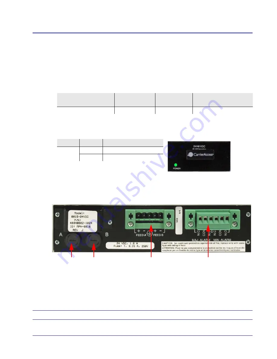
LED

State

Description

Power

Off

DC input missing or failure

Green

DC input present

Power Entry Panel

Alarm Terminal Block

DC Line Input Fuses

(A and B feeds)

Summary of Contents for 8015-24VDC

Page 1: ...MASTERseries 6 01 QUICK START GUIDE Part Number 002 0273 2001 Product Release 6 01 February 2007 ...

Page 2: ...e into any medium electronic mechanical magnetic optical chemical manual or otherwise any part of this manual or software supplied with MASTERseries for any purpose other than the purchaser s personal use without the express written permission of Carrier Access Corporation The Carrier Access Logo is a registered trademark of Carrier Access Corporation FLEXmaster and MASTERseries are trademarks of ...

Page 3: ...he Federal Communications Rules These limits are designed to provide reasonable protection against harmful interference when equipment is operated in a commercial environment This equipment generates uses and can radiate radio frequency energy and if not installed and used in accordance with the instruction manual may cause harmful interference to radio communications Operation of this equipment i...

Page 4: ...l notify the customer as soon as possible Also you will be advised of your right to file a complaint with the FCC if you believe it is necessary 5 The telephone company may make changes in its facilities equipment operations or procedures that could affect the operation of the equipment If this happens the telephone company will provide advance notice in order for you to make necessary modificatio...

Page 5: ...e RJ 41S Refer to ATIS Technical Report No 5 for details on these connectors For Private Leased Line Analog Data Format equipment the type JM8 jack is required Refer to ATIS Technical Report No 5 for details on this connector For Private Leased Line Digital Format equipment in addition to the general requirements for all equipment certain digital connections require that an encoded analog content ...

Page 6: ...d to the facilities of the local telephone company The equipment must also be installed using an acceptable method of connection The customer should be aware that compliance with the above conditions may not prevent degradation of service in some situations Repairs to certified equipment should be coordinated by a representative designated by the supplier Any repairs or alternations made by the us...

Page 7: ...r wet locations Refer to the installation section of this manual for a safe and proper installation procedure All wiring external to this equipment should follow the current provision of the National Electrical Code Notices This manual contains important information and warnings that must be followed to ensure safe operation of the equipment DANGER A DANGER NOTICE INDICATES THE PRESENCE OF A HAZAR...

Page 8: ...st grounding strap and attach it to a metal part of the system unit before handling components If a wrist strap is not available maintain contact with the system unit throughout any procedure requiring ESD protection WARNING INTEGRATED CIRCUITS ICS ARE EXTREMELY SUSCEPTIBLE TO ELECTROSTATIC DISCHARGE UNLESS YOU ARE A QUALIFIED SERVICE TECHNICIAN WHO USES TOOLS AND TECHNIQUES THAT CONFORM TO ACCEPT...

Page 9: ...ier Access Documentation or b credit BUYER for the Product in accordance with Carrier Access s depreciation policy With respect to a warranty defect in the Licensed Software reported to Carrier Access by BUYER during the 90 day software warranty period Carrier Access at its own expense and as its sole obligation and BUYER s exclusive remedy for any breach of the software warranty will use commerci...

Page 10: ...duct License Software any hardware or software or any update upgrade fix or workaround furnished to BUYER will meet BUYER s requirements that the operation thereof including any maintenance or major releases thereto will be uninterrupted or error free THE WARRANTIES IN THIS AGREEMENT REPLACE ALL OTHER WARRANTIES EXPRESSED OR IMPLIED AND ALL OTHER OBLIGATIONS OR LIABILITIES OF CARRIER ACCESS INCLUD...

Page 11: ... Limitation of Remedies x Warranty Product Returns x Introduction Overview 1 Technician Laptop Requirements 1 References 1 Hardware Configurations 1 TDM System part number 8692 0D2 00052 1 ATM System part number 8692 0D2 00075 2 Installation Unpacking 3 About the 2 Slot Chassis 3 Rack Mount Installation 4 Grounding the Chassis 4 Power 5 24 48 VDC Power Supplies 5 DC Power 5 Redundant Power Supplie...

Page 12: ...e Time 22 Using SNTP to Set the System Date Time 23 Opening a Configuration Profile 24 Setting Link Parameters 25 Configuring T1 Links 25 Configuring DS3 Links 27 Configuring System Timing 29 Configuring V 35 Port Parameters 30 Configuring Multi Service Ports 32 Configuring Cross Connects 33 Configuring APS for Link Failures 34 APS Switch Indicator 35 Saving the Configuration 36 Activating the Con...

Page 13: ...guration 44 Alarms and Diagnostics Before you Begin 45 LEDs 45 Alarms 47 Logs 48 Link Alarm Logs 48 System Log 49 Viewing Link and Port Status 50 Performing Link Diagnostics 51 Performing Port Diagnostics 52 Optional IP Setup Overview 53 Setting the IP Address on your PC 53 Changing the IP Address of the MASTERseries 56 Creating a DHCP Pool 56 ...

Page 14: ...xiv MASTERseries Release 6 01 Quick Start Guide Table of Contents ...

Page 15: ...p must be able to connect via RS 232 port or through the USB port with an RS 232 adapter References MASTERseries 6 01 User Manual part number 770 0149 AF Hardware Configurations This document is specifically written to assist with the following configurations TDM System part number 8692 0D2 00052 TDM transport system with 16 T1 ports 4 10 100 LAN ports 2 10 100 Network ports 1 V 35 dual 24 48 VDC ...

Page 16: ...tem with 8 T1 ports 4 10 100 LAN ports 2 10 100 Network ports DS3c 1 V 35 dual 24 48 VDC power and a 2 slot chassis One 2 slot chassis with rack mounts Two 2 slot power supplies FLEXmaster8A TDM Module with 8 T1 ports 4 10 100 LAN ports 2 10 100 Network ports 1 V 35 port FLEXmaster DS3c ATM Module with 3 DS3c ports 2 10 100 Network ports ...

Page 17: ...r any reason carefully repack equipment in the original shipping container with original packing materials if possible 6 If equipment is to be installed later replace equipment in the original shipping container and store in a safe place until you are ready to install it About the 2 Slot Chassis The 2 slot chassis has two application module slots and two power supply slots for redundant power Dime...

Page 18: ...the unit with the brackets to the rack using the screws provided 2 Ground the chassis Grounding the Chassis WARNING THE GROUND TERMINAL ON THE POWER BLOCK MUST BE CONNECTED TO THE FRAME GROUND TO PREVENT POSSIBLE DAMAGE TO THE EQUIPMENT Attach ground wire from the terminal block to the frame ground For more information about the terminal block see Terminal Block on page 6 19 inch Mounting Bracket ...

Page 19: ... DC power protection and isolation when you attach the leads properly Each input has its own return The labels of the power entries vary based on what version of the chassis you have FEED A IN A RTN A operates power supply A FEED B IN B RTN B operates power supply B NOTE The recommended wire gauge for connecting power is 16 to 18 gauge DC Configuration Power Supply Wattage Input Power Feed s Fuse ...

Page 20: ...k with a screwdriver and remove it Attach the leads to the appropriate terminal using the securing screws on the block to tighten them Detailed instructions are below Applying Power Wire Feed A and Feed B to a power source 1 Ensure that no power is present on the two wires to be connected DANGER POSSIBLE SHOCK HAZARD EXISTS PLEASE FOLLOW INSTRUCTIONS CAREFULLY 2 Remove the terminal block from the ...

Page 21: ...crews to clamp wires 6 Ensure that no bare wire shows after the wires are installed 7 Plug the terminal block into the power entry panel 8 Apply power to the chassis 9 A green light should appear on the power LED on the front of the power supply Alarm Contact If you use the alarm contact feature install a ferrite bead part number 010 0051 with a loop Fan Assemblies Both hardware configurations sup...

Page 22: ...adapter module WARNING STATIC PROTECTION IS REQUIRED DURING INSTALLATION PROPER HANDLING GROUNDING AND PRECAUTIONARY ESD MEASURES ARE ESSENTIAL WHEN INSTALLING AND SERVICING PARTS OR MODULES Removing Adapter Strips NOTE Before installing modules and adapters into a 2 slot chassis you must remove the adapter strips To remove an adapter strip Loosen screws and remove the adapter strip from the appli...

Page 23: ...odule When correctly installed the application module faceplate will make contact with the chassis 4 To install a second application module repeat the process for slot 2 Removing an Application Module To remove an application module from a 2 slot chassis remove the two screws that lock the module faceplate to the chassis then push the ejector handle to the right to disengage the connectors Slide t...

Page 24: ...ster module the module with the blinking PST LED 2 Plug the other end of the NMS cable into the COM port of your PC or the port of your VT100 terminal Ferrite Bead Add a ferrite bead part number 010 0365 to the NMS cable of the master module Install the bead with a single loop Installing the Bead 1 Open ferrite bead with the depressions facing up 2 Wrap the NMS cable around the ferrite bead 3 Make...

Page 25: ...required to log in to the MASTERseries Port Setup The MASTERseries software screens are viewable through a VT100 terminal or through a PC using a VT100 terminal emulation software application for example HyperTerminal Use the following parameters needed to configure a system using a VT100 terminal or emulation software Bits per Second 9600 default Data bits 8 Parity None Stop Bits 1 Flow Control N...

Page 26: ...nd the Login prompt appears Default Login admin Default Password nms At this point you can issue commands through the Command Line Interface CLI or launch the Text User Interface TUI To change the password issue the passwd command For details about the CLI see Chapter 11 in the user manual For more information about the TUI see Accessing the Text User Interface on page 13 ...

Page 27: ...k start guide To exit the TUI session press Q for Quit This will return you to the CLI 01 MASTER CARRIER ACCESS MASTERseries Ver 6 01 Sample System Name Alarms sTat Diag pOrt Link tImeslot clK Connect coMmit aPs Setup Flex Quit EDIT CFG 1 RUN CFG 1 LINK DS3 PORT ETH MSRV M Tn ABCD 111 1111 EFGH 111 1111 S En MODULE TYPE 1234 5678 9012 3456 123 1234 12 1234 5678 9012 3456 1 M T1 FLEXmaster16 UUUU U...

Page 28: ...my computer and click OK 3 Click OK to exit the Java Control Panel This works for JRE 1 6 0 on Windows XP and Windows Vista Establishing IP Connectivity to the Master Module The MASTERseries and your PC must be in the same subnet in order to use the GUI To achieve this you can Change the IP address of your PC Change the IP address of the MASTERseries Create a DHCP Pool Detailed procedures for each...

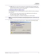
Page 29: ...with Internet Access If you have internet access use the following steps to install the JRE the first time you attempt to log into the GUI 1 Launch your browser and enter the IP address of the MASTERseries in the address bar The default address is http 192 168 2 101 2 Your browser will prompt you to install the missing plug in or ActiveX control NOTE The exact prompt and subsequent dialog displaye...

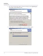
Page 30: ...tart Guide Installation Accessing the GUI 4 Click Install or Yes The License Agreement dialog displays Select Typical Setup and click Accept to start the installation wizard 5 The following dialog appears showing the installation progress ...

Page 31: ...install the JRE from the software CD before you log into the GUI the first time NOTE If you do not have the JRE installed or if you have an earlier version of the JRE installed you will get a blank screen when you attempt to run the GUI 1 Insert the software CD that accompanied your equipment into the CD ROM drive of you PC 2 Locate the JRE installation file jre 1_5_0_09 windows i586 p exe in the ...

Page 32: ...Installation Accessing the GUI 4 The License Agreement dialog similar to the one shown displays Select Typical Setup and click Accept to start the installation wizard 5 A dialog similar to the one shown displays to indicate the installation progress ...

Page 33: ... GUI After installing the JRE use the following steps to access the web based GUI 1 Launch your browser and enter the IP address of your MASTERseries in the address bar The default address is http 192 168 2 101 The Java environment start up screen displays in your browser followed by the Carrier Access login screen 2 Enter the default user name and password and click Login Username admin Password ...

Page 34: ...ERseries Release 6 01 Quick Start Guide Installation Accessing the GUI 3 The home page for the MASTERseries GUI appears The exact appearance of the home page depends on the number and type of modules installed ...

Page 35: ...ulti Service Ports on page 32 Configuring Cross Connects on page 33 Configuring APS for Link Failures on page 34 Saving the Configuration on page 36 Activating the Configuration on page 36 Setting the System Name and Location on page 37 Launching a Telnet Session on page 38 ATM Configuration on page 39 Default Settings The FLEXmaster16 and FLEXmaster8A modules shipped in your hardware configuratio...

Page 36: ...the Setup menu The Setup Date Time window displays You can set the time manually or retrieve the time and date settings from an SNTP server on your network Manually Setting the System Date Time 1 Select Set Manually 2 In the Manual panel select the desired Year Day Month Hour and Minute 3 Click Save The updated date and time display in the status bar Setup Date Time ...

Page 37: ... Select the Synchronization Frequency This value is in seconds from 16 1024 This determines how often the time and date are updated c Select the Packet Transfer Protocol 4 If desired select Enable Timezone Offset to set the timezone name and the number of hours and minutes this timezone is offset from the universal time clock UTC 5 Click Save The updated date and time displays in the status bar Fi...

Page 38: ...sting configuration Use the following steps to access the configuration editor 1 Select Options from the Configuration menu The Configuration Options window displays 2 To edit a previously saved configuration select the number of the desired configuration profile from the Load From pulldown list To create a new profile select New from the pulldown list 3 Click Load to load the selected configurati...

Page 39: ...etails window for the selected link displays The following steps walk you through configuring a link Fill in the fields as described below and click Save to apply your changes These changes will not take effect until you commit and activate the configuration See Saving the Configuration on page 36 To configure a link 1 Open the Link Details window by clicking on a DS1 link in the Tree View 2 The L...

Page 40: ... The Loop Up Code is what you send to the link to force a loop up The default value is 10 You can also choose from 20 30 40 50 60 and 70 Note When used with Nokia radios the industry standard setting of 10 needs to be changed Refer to the MOP for your market for guidelines on how to set this 11 The Facility Data Link Protocol enables performance monitoring statistics gathering The default is Off o...

Page 41: ... and click Save to apply your changes These changes will not take effect until you commit and activate the configuration See Saving the Configuration on page 36 To configure a link 1 Open the DS3 Details window by clicking on a DS3 link in the Tree View 2 The DS3 Status and DS3 Number appear at the top left Verify that you have displayed the desired link For example if you clicked on link 2D01 you...

Page 42: ...routed to the transmitter of the module Local The local loopback is performed using transceiver circuitry This test verifies proper operation of the unit up to the transceiver on the link interface Payload The payload loopback causes the receive signal at the DS3 interface to be internally routed to the transmitter of the module with the exception that the framing and CRC 6 bits are reinserted to ...

Page 43: ...he system timing configuration option from the Setup menu To set timing 1 Select a Clock Mode Internal The timing source is the internal crystal of the module 25ppm This is the default External The timing source is derived from the network using loop timing 2 Select the links to be used as timing sources A primary source must be selected if the clock mode is set to external No Default Indicates th...

Page 44: ...figuration See Saving the Configuration on page 36 To configure a port 1 Open the V 35 Port Configuration window by clicking on a port in the Tree View 2 The card number and Port ID appear at the top left 3 At the Port Name field you can type a name optional The name can be up to 11 alphanumeric characters and names are case sensitive This port name is used in other configuration windows where 4 S...

Page 45: ...plays Link If it is not connected this field displays Idle Destination Link Name displays the name of the link to which the time port is dropped Assigned Timeslots shows the number of timeslots assigned to the connection 7 Set the value for CTS Clear to Send Auto Default Follows RTS Request to Send On Signal is forced high 8 Set the value for DSR Data Set Ready Auto Default Follows DTR Data Termin...

Page 46: ...age 36 To configure a port 1 Open the Multi Service Port Configuration window by clicking on a port in the Tree View 2 The card number and Port ID appear at the top left Verify that you have displayed the desired port The Port Type is MGMT 3 Set the Base rate Options are Nx64 64 kbps operation Default Nx56 56 kbps operation The following fields are read only Destination Type Destination Port ID th...

Page 47: ...he Connect menu The Cross Connect window displays To create a cross connect between links 1 Select the desired link in the Source pane 2 Select the link to which you want to make the timeslot cross connect in the Destination pane 3 If desired enter a name for the cross connect 4 Click Add to create the connection To remove a cross connect between links 1 Select the desired connection in the Connec...

Page 48: ... toggle will take priority over APS The new master will take over and continue to run the current configuration To access the Auto Protection Switch window select the desired card in the Tree View right click to display the context menu and select Auto Protection Switch For each link select the configuration you want to use for the APS In the event of a link failure the system performs an automati...

Page 49: ...elect Yes to return to the original configuration APS Switch Indicator The status bar in the GUI always indicates the currently running configuration for example RUN CFG 1 When an APS switch occurs the display changes to show currently running CFG previously running CFG In the example above RUN CFG 2 1 indicates that an APS switch has occurred The configuration now running is 2 and the configurati...

Page 50: ...on menu The Configuration Options window displays 2 Select the number you want to use for configuration profile from the Save To pulldown list and click Commit Activating the Configuration A saved configuration must be activated before it is used to control the operation of the system If you modified the running configuration you must reactivate the configuration before the changes you made take e...

Page 51: ... 1 Select the System Node from the Tree View The System Details window displays in the Detail View 2 Type a name in the System Name field The name can be up to 64 alphanumeric characters and is case sensitive This information is optional 3 Type the location of the system The name can be up to 64 alphanumeric characters and is case sensitive 4 Type the name or phone number of the main system contac...

Page 52: ...e module must be connected via Ethernet To access the Telnet option select Telnet from the Admin menu A Telnet session launches and connects to the IP address of the card connected to the NMS cable The Login screen for the card displays The Telnet session uses the default VT100 terminal or VT100 terminal emulation software For a Windows PC the default terminal emulation software is typically Hyper...

Page 53: ...onfigure the links selected in step 1 as ATM links 3 Create PVCs as needed 4 Create CES bundles as needed NOTE Configuration changes will not take effect until the changes have been committed to the running configuration For more information about saving see Saving the Configuration on page 36 Because ATM configuration is not available through the GUI this section describes ATM configuration throu...

Page 54: ...STERseries are by default TDM links Decide which links you want use for ATM In this configuration we will map Circuit Emulation CES can be used only on MSRV links M01 M08 1 8 CES converts TDM traffic to ATM backhaul Step 2 Map the Physical Ports to Virtual Ports To get from the TDM side to the ATM side you have to map the connections through the msrv ports The following describes how to map physic...

Page 55: ...and verify that the No field is highlighted Repeat steps 2 through 7 to map 1L02 to 1M02 Note It is possible to map links 1L01 through 1L08 to CES but this example only shows 2 external connections 01 MASTER CARRIER ACCESS MASTERseries Ver 6 01 Alarms sTat Diag pOrt Link tImeslot clK Connect coMmit aPs Setup Flex Quit EDIT CFG 1 RUN CFG 1 No 1L01 T1 DS1_LINK Name Destination Frame T1 ESF IDLE DROP...

Page 56: ...ecially important in the case where the connections are facing a congestion situation where the connections are close to or at 100 of their capacity The higher class of service will get priority for its traffic before the lower class of service The VPI VCI entries depend on how your network is configured In this case 2D01 1 40 and 2D01 1 50 will be used for CES F Flex T Td 01 MASTER CARRIER ACCESS...

Page 57: ...V 64k 1536k Link 1L02 TDMA 1 1 2M03 MSRV 64k 0k Idle 2M04 MSRV 64k 0k Idle 2M05 MSRV 64k 0k Idle 2M06 MSRV 64k 0k Idle 2M07 MSRV 64k 0k Idle 2M08 MSRV 64k 64k Port 1P01 1 2M09 MSRV 64k 0k Idle 2M10 MSRV 64k 0k Idle 2M11 MSRV 64k 0k Idle 2M12 MSRV 64k 0k Idle 2M13 MSRV 64k 0k Idle 2M14 MSRV 64k 0k Idle 2M15 MSRV 64k 0k Idle 2M16 MSRV 64k 0k Idle RED Alarms Clk INT Feb 26 2007 16 24 F Flex E cEs 01 ...

Page 58: ...tion ATM Configuration Clock Settings Modify clock settings as desired Generally the primary source is on a network link facing the switch typically 2D01 Save and Activate the Configuration Save and activate the configuration from the Commit screen K clK M coMmit ...

Page 59: ...s FLEXmaster16 and FLEXmaster8A For more details about individual alarms see the Card Statistics window see Viewing Link and Port Status on page 50 LED State Description PST blinking Passed power on self test Indicates this is the master module for the chassis ALM solid red Alarm failed power on self test State Description solid red OOF out of frame AIS solid green Link is up blinking red LOS soli...

Page 60: ... green Normal the link is up flashing red flashing red LOS Loss of signal solid red solid green OOF out of frame AIS solid yellow solid green FERF Far end receive failure or yellow alarm flashing yellow green Loopback in progress green green Normal the link is up LED State Description Ethernet status light solid yellow Indicates ethernet cable is connected to a device If connecting directly to a N...

Page 61: ...ts currently in alarm Interfaces will appear as d or Diag when a loopback BERT or both are active on the interface Press R to refresh the display A Alarms Alarms sTat Diag pOrt Link tImeslot clK Connect coMmit aPs Setup Flex EDIT CFG 1 RUN CFG 1 LINK DS3 PORT ETH MSRV M Tn ABCD 111 1111 EFGH 111 1111 S En MODULE TYPE 1234 5678 9012 3456 123 1234 12 1234 5678 9012 3456 1 M T1 FLEXmaster16 UUUU UUUU...

Page 62: ...gs Link Alarm logs are available for DS1 and DS3 links The Log View Link Log window displays the alarm history log for the selected link The alarm history log is a circular buffer containing a maximum of 400 entries To display the link alarm log 1 Select the desired link in the Tree View right click to display the context menu and select View Link Log 2 The Alarm Log for the selected link displays...

Page 63: ...window shows a history of system events including configuration changes and error conditions The system event history log is a circular buffer containing a maximum of 400 entries To display the system log select log from the main menu bar and select System Log The system log displays in the Details View window ...

Page 64: ...tus Viewing Link and Port Status The Card Statistics window provides the status of the individual links and ports for each card module To view the statistics right click on the desired card in the Tree View to display the context menu and select Card Statistics The Card Statistics window displays ...

Page 65: ...on a link from the Tree View right click on the link to display the context menu and then select Diagnostics The Diagnostics window displays Here you can view the current link status run Loopback and BERT tests and observe the current test status NOTE Diagnostics for the DS3c 3 Module including Loopbacks are found under the Flex Uni menu in the TUI ...

Page 66: ...s diagnostic loopback and BERT functions on any port in the MASTERseries unit To perform diagnostics on a port from the Tree View right click on the port to display the context menu and then select Diagnostics The Diagnostics window displays Here you can view the current port status run Loopback and BERT tests and observe the current test status ...

Page 67: ...hanging the IP Address of the MASTERseries Creating a DHCP Pool Setting the IP Address on your PC Your PC and MASTERseries must be in the same subnet for TFTP downloads To set the IP address on your PC 1 Go to Start Settings Network Connections Windows XP on Windows 2000 this is Network and Dial up connections 2 Locate the correct Ethernet card and double click it ...

Page 68: ...ERseries Release 6 01 Quick Start Guide Optional IP Setup Setting the IP Address on your PC 3 Click the Properties button 4 From the General tab select Internet Protocol TCP IP and click the Properties button ...

Page 69: ...ress and subnet mask NOTE Your IS department may make these assignments If they do not use the examples in this document which support using the default address of FLEXmaster modules 192 168 2 101 For the examples in this document enter IP address 192 168 2 102 Subnet 255 255 255 0 Click OK 7 Click OK and then close to exit the Network Connections dialogs ...

Page 70: ... are not empty use the following 2 steps to delete DHCP pool table and subnet option table 3 Add the pool Command Description cd 1E1 Change mode to interface 1E1 1E1 shutdown Set 1E1 as out of service 1E1 ip config 198 168 2 101 mask 255 255 255 0 Set the IP address and subnet mask for the interface 1E1 no shutdown Set 1E1 as in service 1E1 cd Change to root mode show ip interface 1e1 Verify the I...

Page 71: ...DHCP Server and the Default Gateway C ipconfig Windows 2000 IP Configuration Ethernet adapter Local Area Connection Connection specific DNS Suffix IP Address 192 168 2 182 Subnet Mask 255 255 255 0 Default Gateway dhcp subnet option 1 3 4 192 168 2 180 Set the subnet options for the pool created in the previous line dhcp Return to root mode show dhcpsrv pools This command displays the currently co...

Page 72: ...58 MASTERseries Release 6 01 Quick Start Guide Optional IP Setup Creating a DHCP Pool ...

Reviews: