background image


CARLOTTI G.&C. Snc  

VIA GHIARADINO 2 

 40054 VEDRANA DI BUDRIO (BO) ITALIA 

TEL: +39 051 6929011  FAX: +39 051 6929110 

www.carlotti-g.it

 - 

[email protected]


The first belt and paddles bring up the product, removing excess soil, and transport it to the second 
belt. 

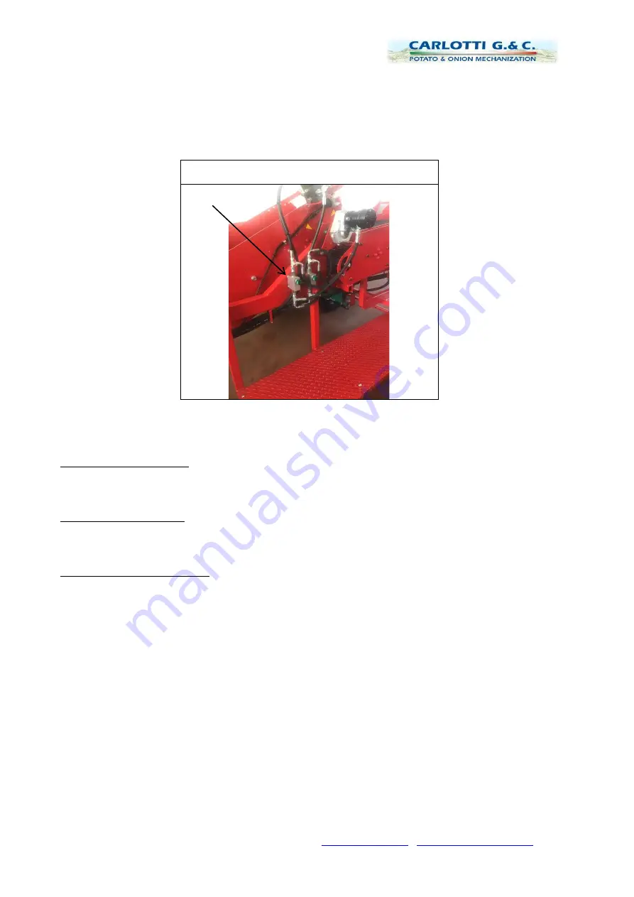
The  two  belts  are  independent  of  each  other  and  have  adjustable  speeds  through  hydraulic 
regulators  positioned  near  the  operators.  (Fig.  3).  Usually  the  first  belt  has  a  speed  greater  than 

30% with respect to that of the second. 
 

Fig. 3 


Belts/tapes speed regulators


All this depends on the type of soil and the maturity of the product. 
To the side of the second belt there are two corridors which transport the product to the rear of the 

machine.  

With potato equipment: 

The excess soil and impurities are discharged to the ground at the end of the second belt, while the 
potatoes are manually placed in the side corridors and transported backwards and unloaded into 

boxes (max. 50 kg), or crates (max 0.6 m3), depending on the configuration of the machine. 

With onion equipment: 

The excess soil and impurities are selected by the operators on board and the onions continue in 

the central part of the belt until they are unloaded into crates (max. 50kg) or crates (max. 0.6 m3) 
depending on the layout. 

Unloading filled containers: 

Once the containers (boxes or boxes) are full, it is necessary to proceed in this manner: 


Stop the progress of the tractor 


Leave the engine running, and the power take-off engaged 


Stop advancement of the belts by acting on the lever of the electrical panel. 


Always avoid a situation where the personnel assigned to use the machine are at the back of 

the machine. A minimum distance greater than 3 meters must be maintained from the range 
of action of the machine. 

Crates and sacks 


Manually unload the full crates and reposition them empty: 

Crates: 


The  tractor  driver,  acting  on  the  lever of  the  electric  panel  activates  the  forklift  lowering 

cylinders. 


Advance with  the  tractor for  approximately 2 meters, always  keeping personnel  at a safe 

distance. 


Act from the opposite wall with the same lever of the electrical panel to lift the forklift. 

Summary of Contents for Green 650/5L

Page 1: ...1 CARLOTTI G C Snc VIA GHIARADINO 2 40054 VEDRANA DI BUDRIO BO ITALIA TEL 39 051 6929011 FAX 39 051 6929110 www carlotti g it direzione carlotti g it USE AND MAINTENANCE MANUAL...

Page 2: ...to digger and harvester onion harvester mod Green 650 5L 2 2 Technical data 2 3 Purpose of the machine and expected conditions of use 2 4 Operation 2 5 Machine operation 2 6 Transport 3 INSTALLATION A...

Page 3: ...ore using it During reading it is advisable to pay particular attention to the movements of the mechanisms to their adjustment and maintenance 2 Before and during work refrain from using alcohol drugs...

Page 4: ...Code To improve circulation within the farm it is necessary to install traffic signs on the internal roadways to ensure that there is sufficient space in the courtyard area to carry out reversal with...

Page 5: ...d the use and maintenance manual stop the tractor engine and remove the key from the panel Danger of cutting ATTENTION Respect the safety distance Danger of becoming entangled and dragged ATTENTION Re...

Page 6: ...42 EC and subsequent amendments known as machine directives The purpose of this manual is to provide the operator with the instructions to safely perform use and maintenance of the GREEN 650 5L potato...

Page 7: ...he manufacturer Model CE marking that certifies the conformity of the machine with the directives of the European Economic Community CEE 2006 42 CE and subsequent modifications Serial number for inter...

Page 8: ...e cannot be used on slopes of more than 15 2 4 Operation After connecting the potato digger and harvester to the tractor see paragraph 3 2 place it on the row to be dug harvested Adjust the power take...

Page 9: ...m3 depending on the configuration of the machine With onion equipment The excess soil and impurities are selected by the operators on board and the onions continue in the central part of the belt unti...

Page 10: ...el ground The operators must wear safety shoes with anti slip soles The platforms and or steps for ascent and descent must always be clean without mud snow or other elements that could make them slipp...

Page 11: ...following are Position the machine on the support foot Fig 5 Fig 5 Machine support foot 3 INSTALLATION AND USE All operations of installation adjustment connection to the tractor etc must be carried...

Page 12: ...g the machine to the tractor Fig 6 Oil Levels 3 2 Connection to the tractor coupling to the towing hook Proceed as follows to connect the drawbar of the machine to the towing hook of the tractor Wear...

Page 13: ...nd harvester to a PTO at 1000 rpm would irreparably damage the hydraulic system Connect the machine to the tractor and operate it at reduced speed During the first activation particular attention shou...

Page 14: ...the first chapter of this booklet 4 1 Assembly and disassembly of belts In the GREEN 650 5 L machine there are 2 types of different belts Collection belt straight bars with applied paddles Sorting bel...

Page 15: ...fixing screws The depth of the discs must be minimal to guarantee the simple linearity of penetration of the collector An excessive depth causes will cause malfunctioning of the digging equipment as i...

Page 16: ...he hook Move the tractor away Secure the mobile structure of the collector by assuming the resting position Remove the plowshares bar see paragraph 4 2 Remove the discs and the feeler roller Place the...

Page 17: ...owshares Damaged items must be immediately replaced or repaired 5 2 Lubrication Always read the warnings and precautions indicated on the lubricant packs Always use gloves for hand protection Before l...

Page 18: ...r must Place the machine on the ground on perfectly level ground Disconnect the machine from the tractor Top up until the aluminium visual indicator light shows the level Never exceed the maximum perm...

Page 19: ...d devices have been adopted to make use and maintenance of the machine safer IT IS STRICTLY FORBIDDEN TO PERFORM MAINTENANCE ON AND OR REMOVE ANY SAFETY DEVICE 1 Emergency mushroom buttons positioned...

Page 20: ...CERTAINTIES OR FOR ANY OTHER INTERVENTION CONTACT THE RETAILER AUTHORISED SERVICE CENTRE OR DIRECTLY TO MANUFACTURER 7 1 Ordering spare parts To order any spare parts refer to the spare parts catalogu...

Page 21: ...linder N Sorting belt regulation valve O Collector regulation valve P Sorter motor Q Collector motor R Motor reducer It is strictly forbidden to modify and or alter in any way the parts devices elemen...

Reviews: