CARLO GAVAZZI
A u t o m a t i o n C o m p o n e n t s
Carlo Gavazzi Controls SpA,
Via Safforze, 8 - 32100
Belluno (Italy)
Tel. +39 0437 355811,
Fax +39 0437 355880
Read carefully the instruction manual.
If the instrument is
used in a manner not specified by the producer, the protection
provided by the instrument may be impaired.
Maintenance:
make sure that the connections are correctly carried out in
order to avoid any malfunctioning or damage to the instrument. To keep
the instrument clean, use a slightly damp cloth; do not use any abrasives
or solvents. We recommend to disconnect the instrument before clean-
ing it.
WARNING:
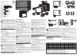
it allows to mount only one module per type, for a maximum
of 3 modules in total. To avoid any damage respect the position of the
modules as shown on table 1. To make sure that the screw tightening
torque is 0.5Nm. ALL THE MOUNTING AND DISASSEMBLY OPERA-
TIONS OF THE INSTRUMENT AND MODULES HAVE TO OCCUR WHEN
POWER SUPPLY AND THE LOADS ARE NOT CONNECTED.
■
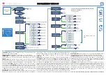
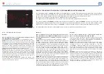
WIRING DIAGRAMS
[1]
2 static opto-mosfet outputs.
[2]
2 relays outputs.
[3]
2 analogue outputs 20mA DC.
[4]
2 analogue outputs 10V DC.
[5]
RS485 serial port.
IMPORTANT:
additional devices provided with
RS485 are connected in parallel. The termination of the serial output
is carried out only on the last instrument of the network, by means
of a jumper between B+ and T.
[6]
RS232 serial port.
IMPORTANT:
the termination must be done by
means of a jumper between B+ and T.
:
the communication RS232 and RS485 ports
can’t be
connected
and used simultaneously.
MC BAC MS module is only supplied with
RS485.
To connect the ethernet or BACnet-IP modules using the RJ45
connector.
[G]
The communication modules are provided with LED indicating the
communication status RX o TX.
Preliminary operations:
remove the protection cover of the contacts
[D]
, using a properly screwdriver.
Lock and sealing the modules:
to lock the modules turning (clockwise)
the properly fixing elements on the corners
[E], [F],
using a properly
screwdriver
[H]
. To seal the instrument use the dedicated holes
[F].
Leggere attentamente il manuale di istruzioni.
Qualora l’ap-
parecchio venisse adoperato in un modo non specificato dal
costruttore, la protezione prevista dall’apparecchio potrebbe
essere compromessa.
Manutenzione:
Per mantenere pulito lo
strumento usare un panno inumidito; non usare abrasivi o solventi. Si
consiglia di scollegare lo strumento prima di eseguire la pulizia.
ATTENZIONE:
è possibile montare un unico modulo per tipo, per un
massimo di tre moduli in totale. Per evitare malfunzionamenti rispettare
la posizione dei moduli come indicato dalla tabella 1. Porre attenzione
alla coppia di serragio applicata alle viti dei morsetti che sia di: 0,5Nm.
TUTTE LE OPERAZIONI DI MONTAGGIO E SMONTAGGIO DELLO STRU-
MENTO E DEI MODULI VANNO ESEGUITE CON ALIMENTAZIONE E
CARICO SCOLLEGATI.
ITALIANO
A
ENGLISH
Lea atentamente el manual de instrucciones.
Si el instru-
mento se usa de modo distinto al indicado por el fabricante, la
protección de seguridad ofrecida por el instrumento podrá
resultar dañada.
Mantenimiento:
para limpiar el equipo utilizar
siempre un trapo ligeramente humedecido, nunca productos abrasivos o
disolventes. Se recomienda desconectar siempre el instrumento antes
de limpiarlo.
ATENCIÓN:
es posible montar un solo módulo por tipo, para un total
máximo de tres módulos. Para evitar daños respete la posición de los
módulos tal como se indica en la tabla 1. Ponga cuidado en que el par
de apriete aplicado sea de: 0,5Nm. TODAS LAS OPERACIONES DE MON-
TAJE Y DESMONTAJE DEL INSTRUMENTO Y DE LOS MÓDULOS DEBE
REALIZARSE CON LA ALIMENTACIÓN Y LA CARGA DESCONECTADAS.
■
CONEXIONES ELÉCTRICAS
[1]
Doble salida estática opto-mosfet.
[2]
Doble salida estática de relé.
[3]
Doble salida analógica de 20mA CC.
[4]
Doble salida analógica de 10V CC.
ESPAÑOL
[5]
Salida de puerto serie RS485. IMPORTANTE: Instrumentos adiciona-
les dotados de RS485 se conectan en paralelo. La terminación de la
salida serie sólo debe realizarse en el último instrumento de la red
mediante un puente entre B+ y T.
[6]
Salida de puerto serie RS232. IMPORTANTE: realice la terminación
mediante un puente entre B+ y T.
:
los puertos de comunicación RS232 y RS485 no pueden utilizarse
ni conectarse al mismo tiempo.
El módulo MC BAC MS se suministra
sólo con RS485.
Para CONECTAR los módulos con salida ethernet o BACnet-IP utilice el
conector RJ45.
[G]
Los módulos de comunicación están dotados de LEDs que señalan
el estado de comunicación RX o TX.
Operación preliminar:
desmonte la ventana de protección de los con-
tactos
[D]
, utilizando un destornillador de punta plana.
Bloqueo y sellado de los módulos:
para bloquear los módulos gire en
el sentido de las agujas del reloj los específicos elementos de fijación de
los extremos de los módulos
[E]
, [
F]
, utilizando un adecuado destornillador
de punta plana
[H]
. Para sellar el equipo use los orificios específicos
[F].
A
Für den ANSCHLUSS der Module an den Ethernet- oder BACnet-IP-
Ausgang den dafür vorgesehenen RJ45-Stecker verwenden.
[G]
Das Kommunikationsmodul ist mit entsprechenden LED ausgestat-
tet, die den Kommunikationsstatus RX oder TX anzeigen.
Vorbereitung:
Das Schutzfenster der Kontakte
[D]
mit einem
Schlitzschraubenzieher entfernen.
Befestigung und Versiegelung der Module:
Die Befestigung der Module
erfolgt über die an den Ecken derselben vorgesehenen
Befestigungselemente
[F]
,
[E]
,
mit Hilfe eines passenden
Schlitzschraubenziehers
[H]
. Das Siegel wird über die hierfür vorgese-
henen Löcher
[F]
angebracht.
Lire attentivement le manuel de l’utilisateur.
Si l’appareil est
utilisé dans des conditions différentes de celles spécifiées par le
fabricant, le niveau de protection prévu par l’instrument peut
être compromis.
Entretien:
Pour nettoyer l’instrument, utiliser
un chiffon humide; ne pas utiliser d’abrasifs ou de solvants. Il faut décon-
necter le dispositif avant de procéder au nettoyage.
ATTENTION:
il est possible de monter un module unique par type, avec
un maximum de trois modules au total. Afin d’éviter les dysfonctionne-
ments, respecter la position des modules comme l’indique le tableau 1.
Faire attention à ce que le couple de serrage appliqué aux vis des bornes
soit de : 0,5Nm. POUR TOUTES LES OPÉRATIONS DE MONTAGE ET
DÉMONTAGE DE L’INSTRUMENT ET DES MODULES IL FAUT QUE L’ALI-
MENTATION ET LA CHARGE SOIENT DÉBRANCHÉES.
■
BRANCHEMENTS ÉLECTRIQUES
[1]
Double sortie statique à opto-mosfet.
[2]
Double sortie statique à relais.
[3]
Double sortie analogique à 20mA CC.
[4]
Double sortie analogique à 10V CC.
[5]
Sortie ports série RS485. IMPORTANT: d’autres instruments pourvus
de RS485 sont branchés en parallèle. La terminaison de la sortie
série doit se faire uniquement sur le dernier instrument du réseau au
moyen d’un cavalier entre les bornes B+ et T.
[6]
Sortie ports série RS232. IMPORTANT: procéder à la terminaison au
moyen d’un cavalier entre les bornes B+ et T.
:
les ports de communication RS232 et RS485 ne peuvent pas être
utilisés et branchés ensemble.
Le module MC BAC MS est fourni uni-
quement avec RS485.
Pour BRANCHER les modules avec sortie Ethernet ou BACnet-IP utiliser
le connecteur RJ45 prévu à cet effet.
[G]
Le module de communication est pourvu de LED spécifiques qui
signalent l’état de communication RX ou TX.
Opération préliminaire:
démonter la fenêtre de protection des contacts
[D]
, en utilisant un tournevis plat approprié.
Bloquer et sceller les modules:
pour bloquer les modules, agir sur les
éléments de fixation prévus à cet effet, situés aux angles des modules
mêmes
[F]
,
[E]
, en utilisant un tournevis plat approprié
[H]
. Poser le
sceau en utilisant les trous spécifiques prévus
[F]
.
A
FRANÇAIS
■
COLLEGAMENTI ELETTRICI
[1]
Doppia uscita statica a opto-mosfet.
[2]
Doppia uscita statica a relè.
[3]
Doppia uscita analogica a 20mA CC.
[4]
Doppia uscita analogica a 10V CC.
[5]
Uscita porte seriali RS485.
IMPORTANTE:
uletriori strumenti provvi-
sti di RS485 sono collegati in parallelo. La terminazione dell’uscita
seriale dev’essere eseguita solo sull’ultimo strumento della rete
mediante un ponticello tra i morsetti B+ e T.
[6]
Uscita porte seriali RS232.
IMPORTANTE:
eseguire la terminazione
mediante un ponticello tra i morsetti B+ e T.
: le porte di comunicazione RS232 e RS485
non possono
essere
usate e connesse insieme.
Il modulo MC BAC MS è provvisto della sola
porta RS485.
Per COLLEGARE i moduli con uscita ethernet o BACnet-IP
utilizzare l’apposito conettore RJ45.
[G]
Il modulo di comunicazione è provvisto di appositi LED segnalanti lo
stato di comunicazione RX o TX.
Operazione preliminare:
smontare la finestra di protezione dei contatti
[D]
, utilizzando un apposito cacciavite a taglio.
Bloccaggio e sigillatura dei moduli:
per bloccare i moduli agire sugli
appositi elementi di fissagio posti agli angoli dei moduli stessi
[F], [E],
utilizzando un adeguato cacciavite a taglio
[H]
. Il sigillo va apposto uti-
lizzando i fori dedicati
[F].
Die Betriebsanleitung aufmerksam lesen.
Sollte das Gerät
nicht gemäss der Herstellerangaben verwendet werden, könnte
der vom Gerät vorgesehene Schutz beeinträchtigt werden.
Wartung:
Das Gerät mit einem feuchten Tuch reinigen; keine
Scheuer- oder Lösemittel verwenden. Das Gerät vor der Reinigung aus-
schalten.
ACHTUNG:
Pro Typ kann nur ein einziges Modul montiert werden, d.h.
insgesamt maximal drei Module. Um Störungen zu vermeiden, sollte die
Position der Module gemäß Tabelle 1 eingehalten werden. Außerdem ist
darauf zu achten, dass das Anzugsmoment der Klemmenschrauben
0,5Nm beträgt. SOWOHL BEI DER MONTAGE, ALS AUCH BEIM AUSBAU
DES GERÄTES UND DER MODULE MÜSSEN STROMVERSORGUNG
UND STROMLAST STETS VORHER ABGETRENNT WERDEN.
■
ELEKTRISCHE ANSCHLÜSSE
[1]
Doppelter statischer Ausgang Opto-mosfet.
[2]
Doppelter statischer Ausgang Relais.
[3]
Doppelter analoger Ausgang 20mA DC.
[4]
Doppelter analoger Ausgang 10V DC.
[5]
Ausgang serielle RS485-Anschlüsse. WICHTIG: Weitere mit RS485
ausgestattete Geräte sind parallel angeschlossen. Der Endverschluss
des seriellen Ausgangs darf nur am letzten Gerät des Netzes mit einer
Überbrückung zwischen den Klemmen B+ und T durchgeführt werden.
[6]
Ausgang serielle RS232-Anschlüsse. WICHTIG: Der Endverschluss
muss mit einer Überbrückung zwischen den Klemmen B+ und T
durchgeführt werden.
:
Die Kommunikationsanschlüsse RS232 und RS485 können nicht
gemeinsam verwendet und angeschlossen werden.
Das MC BAC MS
Modul wird nur mit RS485 geliefert.
A
DEUTSCH
A
WM30_40 IM ML 190312 MODULES cod
. 8021193
[D]
[E]
[F]
IIn
nssttrru
uccttiio
on
n M
Ma
an
nu
ua
all
M
Mo
od
du
ulle
ess W
WM
M3
30
0/
/W
WM
M4
40
0
[G]
[H]
1
2
3
4
2
5
6
7
5
6
7
8
1
2
3
4
M O O2
M O R2
1
2
1
2
1 2
3 4
1 2
3 4
M O A2
M O V2
1 2
M C 485 232
M O A2
M O V2
M O O2
M O R2
M C 485 232
M C BAC SM
1
2
1
2
[1]
[2]
[3]
[4]
[5]
6
7
8
1
2
3
4
6
7
8
1
2
3
4
6
7
8
1
2
3
4
[6]
TTh
ha
an
nk
k y
yo
ou
u
for choosing our products.
G
Grra
az
ziie
e
per aver scelto i nostri prodotti.
W
Wiirr d
da
an
nk
ke
en
n
Ihnen dafür, dass Sie unsere
Produkte gewählt haben.
G
Grra
acciia
ass
por elegir nuestros productos.
M
Me
errccii
d’avoir choisi nos produits.
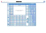
Tab.1
A
B
C
M O O2, [1]
X
M O R2, [2]
X
M O A2, [3]
X
M O V2, [4]
X
M C 485 232, [5], [6]
X
M C ETH
X
M C BACnet-IP
X
MC BAC MS
X
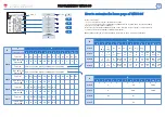
Tab. 2
A
B
C
D
E
F
G
A
-
4kV
4kV
4kV
4kV
4kV
4kV
B
4kV
2kV
NA
4kV
4kV
4kV
4kV
C
4kV
NA
2kV
4kV
4kV
4kV
4kV
D
4kV
4kV
4kV
-
4kV
4kV
4kV
E
4kV
4kV
4kV
4kV
0kV
4kV
4kV
F
4kV
4kV
4kV
4kV
4kV
-
4kV
G
4kV
4kV
4kV
4kV
4kV
4kV
-
A=
Measuring input - Ingressi di misura - Messeingänge - Entrées de mesure - Entr. de medida.
B=
Relay outputs - Uscita relè - Relaisausgänge - Sorties à relais - Salidas de relé.
C=
Static outputs - Uscita statica - Statische Ausgänge - Sorties statiques - Salidas estáticas.
D=
Communication port - Porta di comunicazione - Kommunikations-Schnittstelle - Port de commun - Puerto de comunicación.
E=
Analogue outputs - Uscite analogiche - Analoge Ausgänge - Sortie analogiques - Salidas analógicas.
F=
Digital inputs - Ingressi digitali - Digitaleingänge - Entrées logiques - Entradas digitales
G=
Power supply - Alimentazione - Hilfsstromversorgung - Alimentation auxiliaire - Alimentación auxiliar.
M C BAC SM
Summary of Contents for WM30-96 - PROGRAMMING
Page 1: ...Instruction Manual Display Programming Modular system Class 0 2 A V...
Page 17: ...www gavazzi automation com...
Page 38: ...w ww ww w g ga av va az zz zi i a au ut to om ma at ti io on n c co om m...
Page 43: ...Manual de Instrucciones Display Programaci n Sistema Modular Clase 0 2 A V...
Page 59: ...www gavazzi automation com...
Page 64: ...Manuel de l utilisateur Affichage Programmation Syst me Modulaire Classe 0 2 A V...
Page 80: ...www gavazzi automation com...
Page 85: ...Gebrauchsanleitungen Anzeige Programmierung Modulsystem Klasse 0 2 A V...
Page 101: ...www gavazzi automation com...

