Carel EVD evolution User Manual Download Page 8

7

ENG

“EVD evolution” +030222041 - rel. 1.0 - 01.06.2008

INTRODUCTION

1. 

EVD evolution is a driver for double pole stepper motors designed for to 
control the electronic expansion valve in refrigerant circuits. It is designed 
for DIN rail assembly and is fi tted with plug-in screw terminals. It controls 
refrigerant superheat and optimises the effi  ciency of the refrigerant circuit, 
guaranteeing maximum fl exibility, being compatible with various types 
of  refrigerants  and  valves,  in  applications  with  chillers,  air-conditioners 
and  refrigerators,  the  latter  including  subcritical  and  transcritical  CO2 
systems. It features low superheat, high evaporation pressure (MOP), low 
evaporation pressure (LOP) and high condensing temperature protection, 
and can manage, as an alternative to superheat control, special functions 
such  as  the  hot  gas  bypass,  the  evaporator  pressure  control  (EPR)  and 
control  of  the  valve  downstream  of  the  gas  cooler  in  transcritical  CO2 
circuits.  Together  with  superheat  control,  it  can  manage  an  auxiliary 
control function selected between condensing temperature protection 
and “modulating thermostat”. As regards network connectivity, the driver 
can be connected to either of the following:

a pCO programmable controller to manage the driver via pLAN;

• 

a  pCO  programmable  controller  or  PlantVisorPRO  supervisor  for 

• 

supervision only, via tLAN or RS485/Modbus® respectively. In this case, 
On/Off  control is performed via digital input 1.

The second digital input is available for optimised defrost management. 
Another possibility involves operation as a simple positioner with 4 to 20 
mA or 0 to 10 Vdc analogue input signal. EVD evolution comes with a LED 
board to indicate the operating status, or a graphic display (accessory) that 
can be used to perform installation, following a guided commissioning 
procedure involving setting just 4 parameters: refrigerant, valve, pressure 
sensor, type of main control (chiller, showcase, etc.). The procedure can 
also be used to check that the sensor and valve motor wiring is correct. 
Once  installation  is  complete,  the  display  can  be  removed,  as  it  is  not 
necessary for the operation of the driver, or alternatively kept in place to 
display the signifi cant system variables, any alarms and when necessary 
set the control parameters. The driver can also be setup using a computer 
via the service serial port. In this case, the VPM program (Visual Parameter 
Manager) needs to be installed, downloadable from http://ksa.carel.com, 
and the USB-tLAN converter EVDCNV00E0 connected.

Models  

1.1 

Code

Description

EVD0000E00

EVD evolution - tLAN 

EVD0000E10

EVD evolution - pLAN 

EVD0000E20

EVD evolution - RS485/Modbus® 

EVD0000E01

EVD evolution - tLAN, multiple pack of 10 pcs (*)

EVD0000E11

EVD evolution - pLAN, multiple pack of 10 pcs (*)

EVD0000E21

EVD evolution - RS485/Modbus®, multiple pack of 10 pcs (*)

EVDIS00DE0

Display for EVD evolution, German

EVDIS00EN0

Display for EVD evolution, English

EVDIS00ES0

Display for EVD evolution, Spanish

EVDIS00FR0

Display for EVD evolution, French

EVDIS00IT0

Display for EVD evolution, Italian

EVDIS00PT0

Display for EVD evolution, Portuguese

EVDCON0021 EVD evolution, connector kit (10 pcs) for multiple pack (*)

Tab. 1.a

(*)The  codes  with  multiple  packages  are  sold  without  connectors, 
available separately in code EVDCON0021.

Functions and main characteristics

1.2 

In summary:

electrical connections by plug-in screw terminals;

• 

serial card incorporated in the driver, based on the model (tLAN, pLAN, 

• 

RS485/Modbus®);
compatibility with various types of valves and refrigerants;

• 

activation/deactivation of control via digital input 1 or remote control 

• 

via pLAN, from pCO programmable controller;
superheat control with protection functions for low superheat, MOP, 

• 

LOP, high condensing temperature;
confi guration and programming by display (accessory), by computer 

• 

using the VPM program or by PlantVisor/PlantVisorPro supervisor and 
pCO programmable controller;
commissioning simplifi ed by display with guided procedure for setting 

• 

the parameters and checking the electrical connections;
multi-language  graphic  display,  with  “help”  function  on  various 

• 

parameters;
management of diff erent units of measure (metric/imperial);

• 

parameters  protected  by  password,  accessible  at  a  service  (installer) 

• 

and manufacturer level;
copy the confi guration parameters from one driver to another using 

• 

the removable display;
ratiometric  or  electronic  4  to  20  mA  pressure  transducer,  the  latter 

• 

can  be  shared  between  a  series  of  driver,  useful  for  multiplexed 
applications;
possibility to use S3 and S4 as backup sensors in the event of faults on 

• 

the main sensors S1 and S2;
4  to  20  mA  or  0  to  10  Vdc  input  to  use  the  driver  as  a  positioner 

• 

controlled by an external signal;
management  of  power  failures  with  valve  closing  (if  the  EVBAT200/

• 

EVBAT300 accessory is fi tted);
advanced alarm management.

• 

Series of accessories for EVD evolution

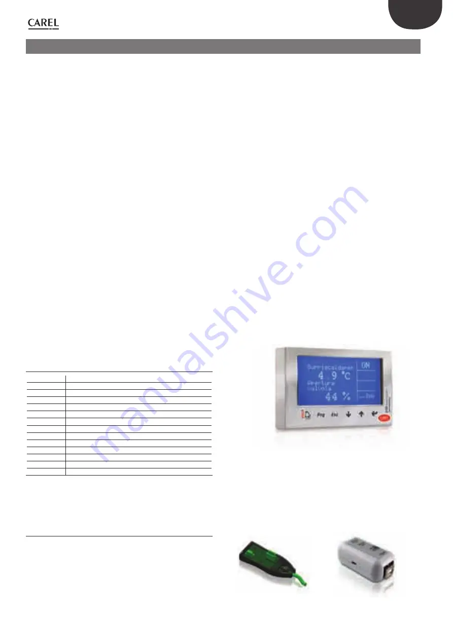
Display (code EVDIS00**0)

Easily  applicable  and  removable  at  any  time  from  the  front  panel  of 
the  driver,  during  normal  operation  displays  all  the  signifi cant  system 
variables, the status of the relay output and recognises the activation of 
the  protection  functions  and  alarms.  During  commissioning,  it  guides 
the  installer  in  setting  the  parameters  required  to  start  the  installation 
and,  once  completed,  can  copy  the  parameters  to  other  drivers.  The 
models diff er in the fi rst settable language, the second language for all 
models is English. EVDIS00**0 can be used to confi gure and monitor all 
the control parameters, accessible via password at a service (installer) and 
manufacturer level.

Fig. 1.a

USB/tLAN converter (code EVDCNV00E0)

The USB-tLAN converter is connected, once the LED board cover has been 
removed,  to  the  service  serial  port  underneath.  Fitted  with  cables  and 
connectors, it can connect EVD evolution directly to a computer, which, 
using the VPM program, can confi gure and program the driver. VPM can 
also be used to update the driver and display fi rmware. See appendix I. 

Fig. 1.b

Summary of Contents for EVD evolution

Page 1: ......

Page 2: ...I n t e g r a t e d C o n t r o l S o l u t i o n s E n e r g y S a v i n g s EVD evolution User manual electronic expansion valve driver...

Page 3: ......

Page 4: ...to open the device in any way other than described in the manual do not drop hit or shake the device as the internal circuits and mechanisms may be irreparably damaged do not use corrosive chemicals s...

Page 5: ......

Page 6: ...oning 17 4 4 Other functions 17 5 CONTROL 18 5 1 Main and auxiliary control 18 5 2 Superheat control 18 5 3 Special control 19 5 4 Auxiliary control 22 6 FUNCTIONS 24 6 1 Inputs and outputs 24 6 2 Con...

Page 7: ......

Page 8: ...play for EVD evolution English EVDIS00ES0 Display for EVD evolution Spanish EVDIS00FR0 Display for EVD evolution French EVDIS00IT0 Display for EVD evolution Italian EVDIS00PT0 Display for EVD evolutio...

Page 9: ...e time required to completely close the electronic valve being controlled while during normal operation the battery is recharged The complete module with batteries code EVBAT00300 and the box for batt...

Page 10: ...seriale di servizio rimuovere il coperchio per potervi accedere Tab 2 a Connection diagram superheat control 2 3 G G0 G G0 VBAT COM1 NO1 1 3 2 4 NET OPEN CLOSE Tx Rx GND DI1 S4 S3 S2 S1 GND DI2 VREF 2...

Page 11: ...idity greater than the 90 or condensing strong vibrations or knocks exposure to continuous water sprays exposure to aggressive and polluting atmospheres e g sulphur and ammonia fumes saline mist smoke...

Page 12: ...he 5 operation was successful UPLOAD the display saves all the values of the parameters on the source driver DOWNLOAD the display copies all the values of the parameters to the target driver RESET all...

Page 13: ...GND DI1 S4 S3 S2 S1 GND DI2 VREF Tx Rx GND DI1 S4 S3 S2 S1 GND DI2 VREF 1 15 3 EVD evolution Fig 2 j Key 1 white A Connection to EVBAT200 300 2 yellow B Connection to electronic pressure sensor SPK 00...

Page 14: ...status of the driver the activation of the protectors any alarms and the status of the relay output Hjgg hXVaYVb 6eZgijgV kVakdaV DC BDE 6A6GB GZaZ 1 2 3 4 5 6 Fig 3 c Key 1 1st variable displayed 2...

Page 15: ...ng the Service 10 parameters E6HHLDG9 Fig 3 e Note if no button is pressed after 5 min the display automatically returns to the standard mode Modifying the Manufacturer parameters The Manufacturer lev...

Page 16: ...on will commence between the two instruments and the driver automatically be enabled for control The main screen will shown on the display which can then be removed and control will be commence when r...

Page 17: ...sure sensor 0 5 to 7 bars for 3 drivers For the first driver select 0 5 to 7 barg For the second and third driver select remote 0 5 to 7 barg Note the range of measurement by default is always in bar...

Page 18: ...an be selected transcritical CO2 hot gas bypass etc as well as so called special control functions which do not involve the superheat activating auxiliary controls that use sensors S3 and or S4 and se...

Page 19: ...superheat temperature in fact corresponds to a situation of probable instability due to the turbulent evaporation process approaching the measurement point of the sensors The expansion valve must the...

Page 20: ...See the EEV system guide 030220810 for further information on calibrating PID control Note when selecting the type of main control both superheat control and special modes the PID control values sugg...

Page 21: ...ressure set point 3 20 290 200 2900 barg psig PID proportional gain 15 0 800 PID integration time 150 0 1000 s PID derivative time 5 0 800 s Tab 5 f Hot gas bypass by temperature This control function...

Page 22: ...le in display mode Control is direct as the pressure increases the valve opens Parameter description Def Min Max UOM SPECIAL Transcritical CO2 coefficient A 3 3 100 800 Transcritical CO2 coefficient B...

Page 23: ...t S4 to modulate the opening of the electronic valve so as to limit the lowering of the temperature read and consequently reach the control set point This is useful in applications such as the multipl...

Page 24: ...Backup sensors on S3 S4 In this case pressure sensor S3 and temperature sensor S4 will be used to replace sensors S1 and S2 respectively in the event of faults on one or both so as to guarantee a high...

Page 25: ...9 3 barg Ratiometric OUT 0 to 5 V Electronic OUT 4 to 20 mA 1 to 4 2 barg 0 4 to 9 2 barg 1 to 9 3 barg 0 to 17 3 barg 0 4 to 34 2 barg 0 to 34 5 barg 0 to 45 barg 0 5 to 7 barg 0 to 10 barg 0 to 18 2...

Page 26: ...at start evaporator valve capacity ratio 50 0 100 Tab 6 i This parameter should be set based on the ratio between the rated cooling capacity of the evaporator and the valve e g rated evaporator cooli...

Page 27: ...reaching 0 steps plus a further number of steps so as to guarantee complete closing Following the stop phase the valve returns to standby t t t t OFF ON R OFF ON ST OFF ON S OFF ON A T4 Fig 6 d Key A...

Page 28: ...s only valid when the driver is performing superheat control Unblock valve is an automatic safety procedure that attempts to unblock a valve that is supposedly blocked based on the control variables s...

Page 29: ...tection threshold 5 40 72 set point superheat K R LowSH protection integration time 15 0 800 s ALARM CONFIGURATION Low superheat alarm delay LowSH 0 alarm disabled 300 0 18000 s Tab 7 b When the super...

Page 30: ...ure alarm delay MOP 0 alarm disabled 600 0 18000 s Tab 7 d The integration time is set automatically based on the type of main control When the evaporation temperature rises above the MOP threshold th...

Page 31: ...will not resume based on the activation of the protector but rather on the reduction in the outside temperature The system will therefore remain in the best operating conditions a little below the thr...

Page 32: ...emote 0 to 10 barg remote 0 to 18 2 barg remote 0 to 25 barg remote 0 to 30 barg remote 0 to 44 8 barg External signal 4 to 20 mA Ratiometric 1 to 9 3 barg I 16 143 A Main control Multiplexed cabinet...

Page 33: ...n Current cooling capacity Control set point Superheat Suction temperature Evaporation temperature Evaporation pressure Condensing temperature Condensing pressure Modulating thermostat temperature EPR...

Page 34: ...50 60 76 Temperature S4 MAXIMUM alarm value C F A 47 46 C Temperature S4 MAXIMUM alarm value 105 Temperature S4 MINIMUM alarm value 200 392 C F A 45 44 CONTROL A Superheat set point 11 LowSH thre shol...

Page 35: ...e of variable A analogue D digital I integer Unit of measure 8 1 In the configuration parameters menu with access by manufacturer password the user can choose the unit of measure for the driver intern...

Page 36: ...irmware version Tab 8 b Digital input status 0 open 1 closed Note the readings of sensors S1 S2 S3 S4 are always displayed regardless of whether or not the sensor is connected Variables only accessibl...

Page 37: ...R Relay status 0 0 1 D 9 8 R ALARMS LOP low evaporation temperature 0 0 1 D 10 9 R MOP high evaporation temperature 0 0 1 D 11 10 R LowSH low superheat 0 0 1 D 12 11 R HiTcond high condensing tempera...

Page 38: ...nfiguration parameter automatic Depends on parameter Sensor S1 alarm manage ment Check the sensor connections Check the Sensor S1 alarm management and Pressure S1 MINIMUM MAXI MUM alarm value paramete...

Page 39: ...g normal operation the relay contact is closed and is open only in standby There is no change in the event of alarms solenoid valve relay alarm during normal operation the relay contact is closed and...

Page 40: ...ealarmisnotlinkedtoanyprotectionfunction It features a threshold and a delay and is useful in the event of sensor or valve malfunctions to protect the compressor using the relay to control the solenoi...

Page 41: ...driver will remain in standby however control will be able to start if the digital input is closed In this case it will start with current cooling capacity 100 case 4 unit in control digital input DI1...

Page 42: ...reaching operating conditions is very low for a few minutes Check that the LowSH threshold is greater than the superheat value measured and that the corresponding protection is activated integration...

Page 43: ...he LOP protection threshold is at the required saturated evaporation temperature between the rated evaporation temperature of the unit and the corre sponding temperature at the calibration of the low...

Page 44: ...iometric pressure sensor 0 to 5 V resolution 0 1 FS measurement error 2 FS maximum 1 typical electronic pressure sensor 4 to 20 mA resolution 0 5 FS measurement error 8 FS maximum 7 typical electronic...

Page 45: ...2 a Then the user can choose to directly access to the list of parameters for the EVD evolution 1 saved to EEPROM select tLAN This is done in real time ONLINE mode at the top right set the network add...

Page 46: ...e code Different firmware versions may cause compatibility problems Setting the default parameters 12 4 When the program opens select the model from the range and load the associated list of parameter...

Page 47: ...46 ENG EVD evolution 030222041 rel 1 0 01 06 2008...

Page 48: ......

Page 49: ...CAREL S p A Via dell Industria 11 35020 Brugine Padova Italy Tel 39 049 9716611 Fax 39 049 9716600 e mail carel carel com www carel com Agenzia Agency 030222041 rel 1 0 01 06 2008...

Reviews: