Carel EVD evolution User Manual Download Page 42

41

ENG

“EVD evolution” +030222041 - rel. 1.0 - 01.06.2008

TROUBLEShOOTING

10. 

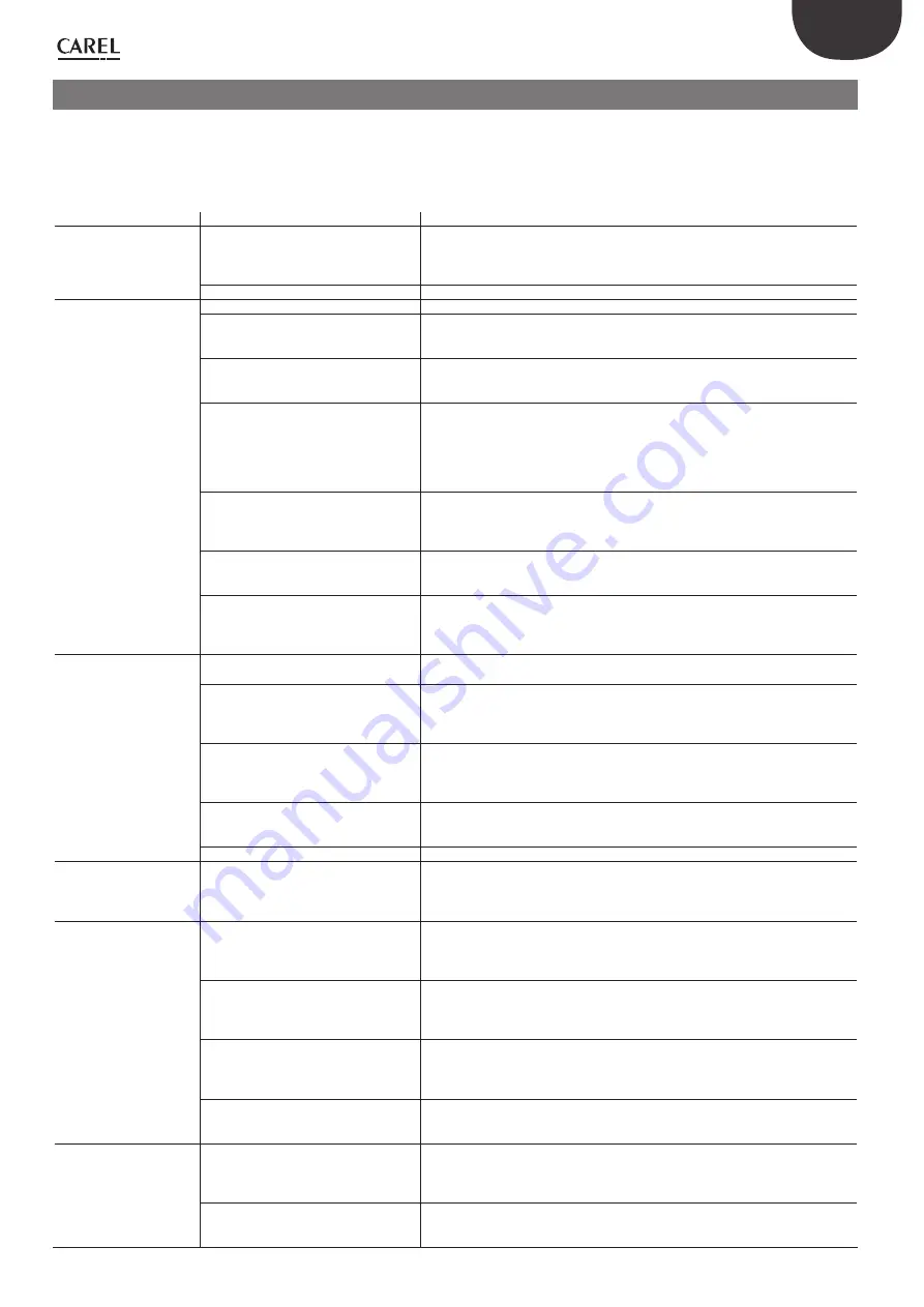
The following table lists a series of possible malfunctions that may occur 
when starting and operating the driver and the electronic valve. These 
cover  the  most  common  problems  and  are  provided  with  the  aim  of 
offering an initial response for resolving the problem.

PROBLEM

CAUSE

SOLUTION

The superheat value measu-
red is incorrect

The probe does not measure correct values Check that the pressure and the temperature measured are correct and that the probe 

position is correct. Check that the minimum and maximum pressure parameters for the 
pressure transducer set on the driver correspond to the range of the pressure probe 
installed. Check the correct probe electrical connections.

The type of refrigerant set is incorrect

Check and correct the type of refrigerant parameter.

Liquid returns to the com-
pressor during control

The type of valve set is incorrect

Check and correct the type of valve parameter.

The valve is connected incorrectly (rotates 
in reverse) and is open

Check the movement of the valve by placing it in manual control and closing or ope-
ning it completely. One complete opening must bring a decrease in the superheat and 
vice-versa. If the movement is reversed, check the electrical connections.

The superheat set point is too low

Increase the superheat set point. Initially set it to 12 °C and check that there is no 
longer return of liquid. Then gradually reduce the set point, always making sure there is 
no return of liquid. 

Low superheat protection ineffective

If the superheat remains low for too long with the valve that is slow to close, increase 
the low superheat threshold and/or decrease the low superheat integration time. 
Initially set the threshold 3 °C below the superheat set point, with an integration time 
of 3-4 seconds. Then gradually lower the low superheat threshold and increase the low 
superheat integration time, checking that there is no return of liquid in any operating 
conditions.

Stator broken or connected incorrectly

Disconnect the stator from the valve and the cable and measure the resistance of the 
windings using an ordinary tester.
The resistance of both should be around 36 ohms. Otherwise replace the stator. Finally, 
check the electrical connections of the cable to the driver.

Valve stuck open

Check if the superheating is always low (<2 °C) with the valve position permanently at 
0 steps. If so, set the valve to manual control and close it completely. If the superheat is 
always low, check the electrical connections and/or replace the valve.

The “valve opening at start” parameter 
is too high on many cabinets in which 
the control set point is often reached (for 
multiplexed cabinets only)

Decrease the value of the “Valve opening at start” parameter on all the utilities, making 
sure that there are no repercussions on the control temperature.

Liquid returns to the com-
pressor only after defrosting 
(for multiplexed cabinets 
only)

The pause in control after defrosting is too 
short

Increase the value of the “valve control delay after defrosting” parameter.

The superheat temperature measured 
by the driver after defrosting and before 
reaching operating conditions is very low 
for a few minutes

Check that the LowSH threshold is greater than the superheat value measured and that 
the corresponding protection is activated (integration time >0 s). If necessary, decrease 
the value of the integration time.

The superheat temperature measured by 
the driver does not reach low values, but 
there is still return of liquid to the compres-
sor rack 

Set more reactive parameters to bring forward the closing of the valve: increase the 
proportional factor to 30, increase the integration time to 250 s and increase the deri-
vative time to 10 sec.

Many cabinets defrosting at the same time Stagger the start defrost times. If this is not possible, if the conditions in the previous 

two points are not present, increase the superheat set point and the LowSH thresholds 
by at least 2 °C on the cabinets involved.

The valve is significantly oversized

Replace the valve with a smaller equivalent. 

Liquid returns to the com-
pressor only when starting 
the controller (after being 
OFF)

The “valve opening at start” parameter is 
set too high

Check the calculation in reference to the ratio between the rated cooling capacity of 
the evaporator and the capacity of the valve; if necessary, lower the value.

The superheat value swings 
around the set point with an 
amplitude greater than 4°C

The condensing pressure swings

Check the controller condenser settings, giving the parameters “blander” values (e.g. 
increase the proportional band or increase the integration time). Note: the required sta-
bility involves a variation /- 0.5 bars. If this is not effective or the settings cannot 
be changed, adopt electronic valve control parameters for perturbed systems 

The superheat swings even with the valve 
set in manual control (in the position cor-
responding to the average of the working 
values)

Check for the causes of the swings (e.g. low refrigerant charge) and resolve where pos-
sible. If not possible, adopt electronic valve control parameters for perturbed systems.

The superheat does NOT swing with the 
valve set in manual control (in the position 
corresponding to the average of the 
working values)

As a first approach , decrease (by 30 to 50 %) the proportional factor. Subsequently try 
increasing the integration time by the same percentage. In any case, adopt parameter 
settings recommended for stable systems.

The superheat set point is too low

Increase the superheat set point and check that the swings are reduced or disappear. 
Initially set 13 °C, then gradually reduce the set point, making sure the system does not 
start swinging again and that the unit temperature reaches the control set point. 

In the start-up phase with 
high evaporator tempe-
ratures, the evaporation 
pressure is high

MOP protection disabled or ineffective

Activate the MOP protection by setting the threshold to the required saturated eva-
poration temperature (high evaporation temperature limit for the compressors) and 
setting the MOP integration time to a value above 0 (recommended 4 seconds). To 
make the protection more reactive, decrease the MOP integration time.

Refrigerant charge excessive for the system 
or extreme transitory conditions at start-up 
(for cabinets only).

Apply a “soft start” technique, activating the utilities one at a time or in small groups. If 
this is not possible, decrease the values of the MOP thresholds on all the utilities.

Summary of Contents for EVD evolution

Page 1: ......

Page 2: ...I n t e g r a t e d C o n t r o l S o l u t i o n s E n e r g y S a v i n g s EVD evolution User manual electronic expansion valve driver...

Page 3: ......

Page 4: ...to open the device in any way other than described in the manual do not drop hit or shake the device as the internal circuits and mechanisms may be irreparably damaged do not use corrosive chemicals s...

Page 5: ......

Page 6: ...oning 17 4 4 Other functions 17 5 CONTROL 18 5 1 Main and auxiliary control 18 5 2 Superheat control 18 5 3 Special control 19 5 4 Auxiliary control 22 6 FUNCTIONS 24 6 1 Inputs and outputs 24 6 2 Con...

Page 7: ......

Page 8: ...play for EVD evolution English EVDIS00ES0 Display for EVD evolution Spanish EVDIS00FR0 Display for EVD evolution French EVDIS00IT0 Display for EVD evolution Italian EVDIS00PT0 Display for EVD evolutio...

Page 9: ...e time required to completely close the electronic valve being controlled while during normal operation the battery is recharged The complete module with batteries code EVBAT00300 and the box for batt...

Page 10: ...seriale di servizio rimuovere il coperchio per potervi accedere Tab 2 a Connection diagram superheat control 2 3 G G0 G G0 VBAT COM1 NO1 1 3 2 4 NET OPEN CLOSE Tx Rx GND DI1 S4 S3 S2 S1 GND DI2 VREF 2...

Page 11: ...idity greater than the 90 or condensing strong vibrations or knocks exposure to continuous water sprays exposure to aggressive and polluting atmospheres e g sulphur and ammonia fumes saline mist smoke...

Page 12: ...he 5 operation was successful UPLOAD the display saves all the values of the parameters on the source driver DOWNLOAD the display copies all the values of the parameters to the target driver RESET all...

Page 13: ...GND DI1 S4 S3 S2 S1 GND DI2 VREF Tx Rx GND DI1 S4 S3 S2 S1 GND DI2 VREF 1 15 3 EVD evolution Fig 2 j Key 1 white A Connection to EVBAT200 300 2 yellow B Connection to electronic pressure sensor SPK 00...

Page 14: ...status of the driver the activation of the protectors any alarms and the status of the relay output Hjgg hXVaYVb 6eZgijgV kVakdaV DC BDE 6A6GB GZaZ 1 2 3 4 5 6 Fig 3 c Key 1 1st variable displayed 2...

Page 15: ...ng the Service 10 parameters E6HHLDG9 Fig 3 e Note if no button is pressed after 5 min the display automatically returns to the standard mode Modifying the Manufacturer parameters The Manufacturer lev...

Page 16: ...on will commence between the two instruments and the driver automatically be enabled for control The main screen will shown on the display which can then be removed and control will be commence when r...

Page 17: ...sure sensor 0 5 to 7 bars for 3 drivers For the first driver select 0 5 to 7 barg For the second and third driver select remote 0 5 to 7 barg Note the range of measurement by default is always in bar...

Page 18: ...an be selected transcritical CO2 hot gas bypass etc as well as so called special control functions which do not involve the superheat activating auxiliary controls that use sensors S3 and or S4 and se...

Page 19: ...superheat temperature in fact corresponds to a situation of probable instability due to the turbulent evaporation process approaching the measurement point of the sensors The expansion valve must the...

Page 20: ...See the EEV system guide 030220810 for further information on calibrating PID control Note when selecting the type of main control both superheat control and special modes the PID control values sugg...

Page 21: ...ressure set point 3 20 290 200 2900 barg psig PID proportional gain 15 0 800 PID integration time 150 0 1000 s PID derivative time 5 0 800 s Tab 5 f Hot gas bypass by temperature This control function...

Page 22: ...le in display mode Control is direct as the pressure increases the valve opens Parameter description Def Min Max UOM SPECIAL Transcritical CO2 coefficient A 3 3 100 800 Transcritical CO2 coefficient B...

Page 23: ...t S4 to modulate the opening of the electronic valve so as to limit the lowering of the temperature read and consequently reach the control set point This is useful in applications such as the multipl...

Page 24: ...Backup sensors on S3 S4 In this case pressure sensor S3 and temperature sensor S4 will be used to replace sensors S1 and S2 respectively in the event of faults on one or both so as to guarantee a high...

Page 25: ...9 3 barg Ratiometric OUT 0 to 5 V Electronic OUT 4 to 20 mA 1 to 4 2 barg 0 4 to 9 2 barg 1 to 9 3 barg 0 to 17 3 barg 0 4 to 34 2 barg 0 to 34 5 barg 0 to 45 barg 0 5 to 7 barg 0 to 10 barg 0 to 18 2...

Page 26: ...at start evaporator valve capacity ratio 50 0 100 Tab 6 i This parameter should be set based on the ratio between the rated cooling capacity of the evaporator and the valve e g rated evaporator cooli...

Page 27: ...reaching 0 steps plus a further number of steps so as to guarantee complete closing Following the stop phase the valve returns to standby t t t t OFF ON R OFF ON ST OFF ON S OFF ON A T4 Fig 6 d Key A...

Page 28: ...s only valid when the driver is performing superheat control Unblock valve is an automatic safety procedure that attempts to unblock a valve that is supposedly blocked based on the control variables s...

Page 29: ...tection threshold 5 40 72 set point superheat K R LowSH protection integration time 15 0 800 s ALARM CONFIGURATION Low superheat alarm delay LowSH 0 alarm disabled 300 0 18000 s Tab 7 b When the super...

Page 30: ...ure alarm delay MOP 0 alarm disabled 600 0 18000 s Tab 7 d The integration time is set automatically based on the type of main control When the evaporation temperature rises above the MOP threshold th...

Page 31: ...will not resume based on the activation of the protector but rather on the reduction in the outside temperature The system will therefore remain in the best operating conditions a little below the thr...

Page 32: ...emote 0 to 10 barg remote 0 to 18 2 barg remote 0 to 25 barg remote 0 to 30 barg remote 0 to 44 8 barg External signal 4 to 20 mA Ratiometric 1 to 9 3 barg I 16 143 A Main control Multiplexed cabinet...

Page 33: ...n Current cooling capacity Control set point Superheat Suction temperature Evaporation temperature Evaporation pressure Condensing temperature Condensing pressure Modulating thermostat temperature EPR...

Page 34: ...50 60 76 Temperature S4 MAXIMUM alarm value C F A 47 46 C Temperature S4 MAXIMUM alarm value 105 Temperature S4 MINIMUM alarm value 200 392 C F A 45 44 CONTROL A Superheat set point 11 LowSH thre shol...

Page 35: ...e of variable A analogue D digital I integer Unit of measure 8 1 In the configuration parameters menu with access by manufacturer password the user can choose the unit of measure for the driver intern...

Page 36: ...irmware version Tab 8 b Digital input status 0 open 1 closed Note the readings of sensors S1 S2 S3 S4 are always displayed regardless of whether or not the sensor is connected Variables only accessibl...

Page 37: ...R Relay status 0 0 1 D 9 8 R ALARMS LOP low evaporation temperature 0 0 1 D 10 9 R MOP high evaporation temperature 0 0 1 D 11 10 R LowSH low superheat 0 0 1 D 12 11 R HiTcond high condensing tempera...

Page 38: ...nfiguration parameter automatic Depends on parameter Sensor S1 alarm manage ment Check the sensor connections Check the Sensor S1 alarm management and Pressure S1 MINIMUM MAXI MUM alarm value paramete...

Page 39: ...g normal operation the relay contact is closed and is open only in standby There is no change in the event of alarms solenoid valve relay alarm during normal operation the relay contact is closed and...

Page 40: ...ealarmisnotlinkedtoanyprotectionfunction It features a threshold and a delay and is useful in the event of sensor or valve malfunctions to protect the compressor using the relay to control the solenoi...

Page 41: ...driver will remain in standby however control will be able to start if the digital input is closed In this case it will start with current cooling capacity 100 case 4 unit in control digital input DI1...

Page 42: ...reaching operating conditions is very low for a few minutes Check that the LowSH threshold is greater than the superheat value measured and that the corresponding protection is activated integration...

Page 43: ...he LOP protection threshold is at the required saturated evaporation temperature between the rated evaporation temperature of the unit and the corre sponding temperature at the calibration of the low...

Page 44: ...iometric pressure sensor 0 to 5 V resolution 0 1 FS measurement error 2 FS maximum 1 typical electronic pressure sensor 4 to 20 mA resolution 0 5 FS measurement error 8 FS maximum 7 typical electronic...

Page 45: ...2 a Then the user can choose to directly access to the list of parameters for the EVD evolution 1 saved to EEPROM select tLAN This is done in real time ONLINE mode at the top right set the network add...

Page 46: ...e code Different firmware versions may cause compatibility problems Setting the default parameters 12 4 When the program opens select the model from the range and load the associated list of parameter...

Page 47: ...46 ENG EVD evolution 030222041 rel 1 0 01 06 2008...

Page 48: ......

Page 49: ...CAREL S p A Via dell Industria 11 35020 Brugine Padova Italy Tel 39 049 9716611 Fax 39 049 9716600 e mail carel carel com www carel com Agenzia Agency 030222041 rel 1 0 01 06 2008...

Reviews: