E
CLIPSE
Service
Manual
Carefree of Colorado
10
052547-301r10
R
EPLACING THE
G
AS
S
HOCK
CAUTION
The gas shock has approximately 85 lbs. of pressure in the closed position. A
pressurized shock can open rapidly when removed or released causing personal injury and property
damage.
1. Open the awning.
NOTE:
The arm may not completely open when the shock has lost pressure or it is removed. It may be
necessary to pull the arm out and away from the vehicle to open the awning.
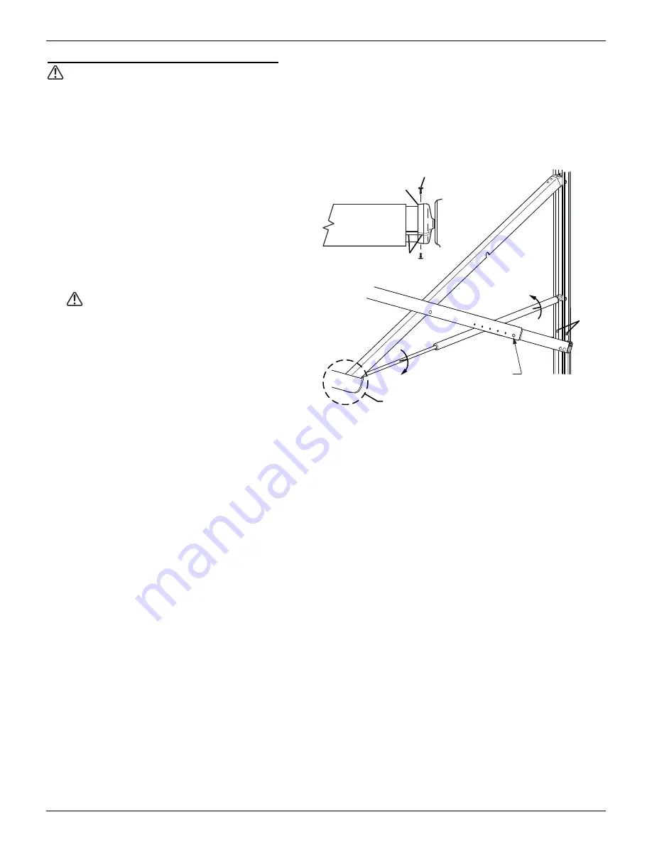
2. Remove the stop bolts and save.
3. Remove the two square drive screws attaching
the end cap to the roller tube, then separate
the roller tube and end cap. It will be
necessary to hold the roll bar and motor arm.
Allow the arm to extend out.
4. Use a scaffold or similar device to support the
roller tube.
CAUTION
Do not allow the roller tube
to drop toward the ground. The twisting
motion can cause serious damage to the
idler arm.
5. Support the arm in the area shown.
6. Unscrew the shock barrel from the clevis in the
mounting channel.
Tip: Wearing a pair of rubber gloves will aid in gripping the surfaces of the shock.
7. Unscrew the shaft from the clevis in the arm joint. Set old shock aside.
NOTE:
It may be necessary to use vice grips or pliers on the old shock to unscrew the shock from the
clevis. DO NOT use vice grips or pliers on the new shock. Damage to the surface of the shaft or
damage to the barrel can cause the new shock to not work.
8. Unpack the new shock and carefully allow it to extend to its maximum length.
9. Insert the new shock between the upright struts.
10. Coat the threads of the shaft of the new shock with a non-permanent thread lock (i.e. loctite) then screw
the rod into the clevis of the arm elbow. Hand-tighten only.
11. Lift and hold the arm up in the area indicated in Figure 9. The arm should be unfolded and extended as
far as possible.
12. Coat the threads of the barrel of the new shock with a non-permanent thread lock (i.e. loctite) then
screw the barrel into the clevis in the mounting channel. Hand-tighten only. It will be necessary to grip
and hold the shaft while turning the barrel.
13. Align the roll bar with the end cap on the arm assembly. Rotate the end cap until the slot in the cap
aligns with the empty slot in the roller assembly, and then press the roller assembly fully into the cap.
The end cap must seat squarely over the end of the roller assembly when complete.
14. Secure the end cap to the roller assembly using two #10 x 5/8 square-drive screws.
15. Partially retract the awning. It may be necessary to lightly pull down on the lower arm at the mounting
channel until the rollers are past the location of the stop bolts. Always pull down from the bottom of the
arm to avoid pinching.
16. Reinstall the stop bolts removed in step 2.
E0054
Loosen
Loosen
Stop
Bolts
Set Arm at
Minimum Pitch
Support and Lift in this area
Align Slots
End Cap
#10 x 5/8 Screw (x2)
Summary of Contents for ECLIPSE 2015
Page 4: ......


