


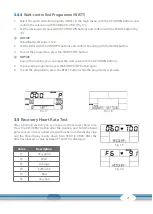
15
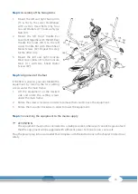
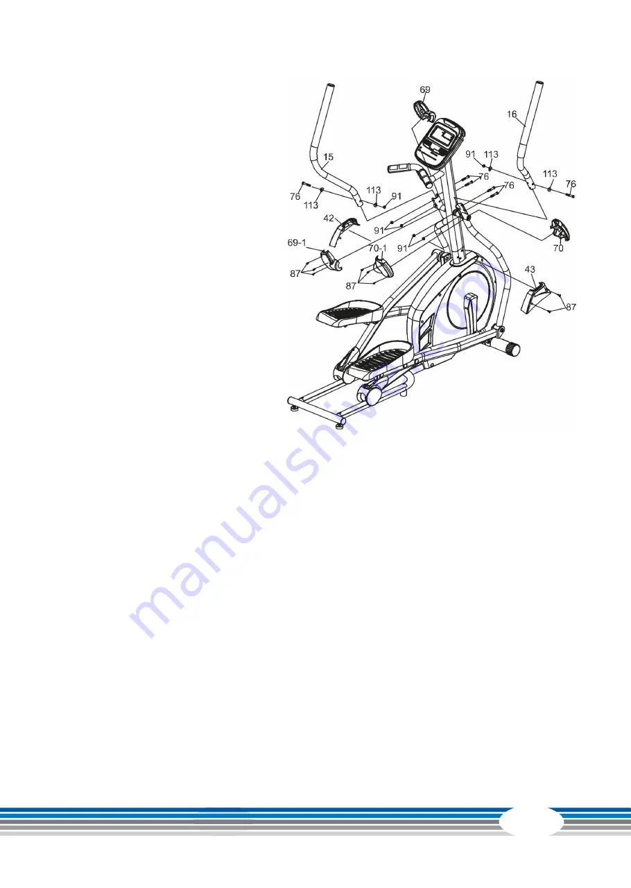
Step 4:
Assembly of the Swing Arms
1. Mount the left and right Swing Arm
(15 & 16) to the Lower Handlebars
with six Hex Head Bolts (76), four
Curved Washers (113) and six Nyloc
Nuts (91).
2. Mount the left Front Handle Bar
Cover (69) together with the left Rear
Handle Bar Cover (69-1) to the left
Lower Handle Bar with three Sheet
Metal Screws (87). Repeat this step
for the other side.
3. Mount the left and right Console
Mast Cover (42 & 43) to the Console
Mast (11) with two Sheet Metal
Screws (87).
Step 5:
Alignment of the feet
If the floor is uneven, you can stabilize the
equipment by turning the two setting
screws under the main frame.
1. Lift the equipment on the desired
side and rotate the setting screws
under the main frame.
2. Rotate the screws clockwise in order to remove them and to raise the equipment.
3. Rotate them counterclockwise in order to lower the equipment.
Step 6:
Connecting the equipment to the mains supply
࣑
ATTENTION
The equipment must not be connected to a multiple socket, otherwise it cannot be guaranteed
that the equipment will be supplied with sufficient power. Technical errors can result.
Plug the power plug into a wall outlet that complies with the instructions in the chapter on electrical
safety.


