background image

EX

40


13

3.2

 Assembly instructions

Before starting assembly, look carefully through the individual assembly steps shown 

and assemble the equipment in the order indicated.

Step 1:

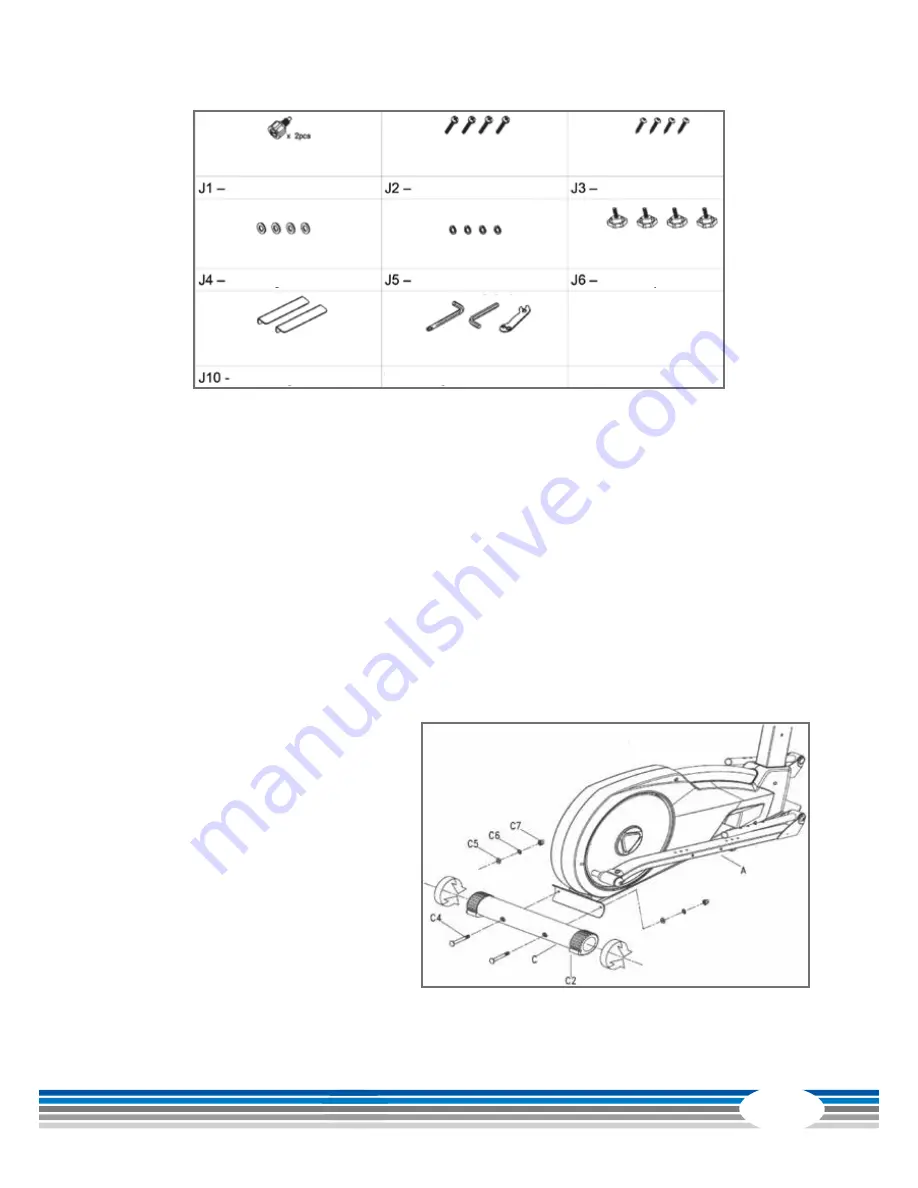
 Assembly of the rear supporting foot

First remove the screws (C4), washers (C5), spring washers (C6) and nuts (C7) from the 

rear supporting foot (C). Next, put the screws (C4) through the rear supporting foot (C) 

and the bracket on the frame (A). Then secure the supporting foot with two washers 

(C5), two spring washers (C6) and two nuts (C7).

Turning knobs

Washers M6

Holders

Screws M5*8L

Spring washers M6

Tools

Screws M4*12L

Turning knobs

Summary of Contents for CST-EX40-BG

Page 1: ...Elliptical cross trainer EX40 Assembly and Operating Instructions Art No CST EX40 BG...

Page 2: ...EX40 2...

Page 3: ...are informed about these instructions and its content in advance In case of doubt a responsible person must supervise the use of the equipment This equipment has been manufactured according to the lat...

Page 4: ...instructions 13 4 OPERATING INSTRUCTIONS 19 4 1 Console display 19 4 2 Button functions 21 4 3 User memory 22 4 4 Programs 23 4 4 1 MAN Manual program 23 4 4 2 Pre set programs 24 4 4 3 Watt based pr...

Page 5: ...5 7 DISPOSAL 38 8 ORDERING ACCESSORIES 39 9 ORDERING SPARE PARTS 40 9 1 Service hotline 40 9 2 Serial number and model name 40 9 3 Parts list 41 9 4 Exploded drawing 43...

Page 6: ...increments User memory 5 Total number of workout programs 19 Manual programs 1 Preset programs 12 Watt based programs 1 Heart rate controlled programs 4 User defined program 1 Balance mass 28 kg Gear...

Page 7: ...nsupervised access to the equipment Before starting your training make yourself familiar with all of the equipment s functions and setting options Have an expert explain the correct usage of the produ...

Page 8: ...ns to either the power cable or the mains plug If the power cable or the plug are damaged or defective contact your authorized contract partner Do not use the equipment in the meantime Do not keep ele...

Page 9: ...ring assembly Do not leave any tools and packaging materials like plastic sheeting laying around to avoid danger of suffocation for children Assemble the equipment on an underlay mat or on the cardboa...

Page 10: ...most common errors and how to repair them If the equipment still does not work properly please contact your contract partner Problem Cause Solution Drive discs wobble or make noises Drive pulley is lo...

Page 11: ...The following routine work must be done in the specified time intervals Part Weekly Monthly 2x annually Annually Display console C I Lubricate the moving parts I Plastic cover C I Screws and cable con...

Page 12: ...d in the illustration including a power cable with mains plug If one of the illustrated parts is missing please contact your contract partner Frame Console mast Front supporting foot Rear supporting f...

Page 13: ...upporting foot First remove the screws C4 washers C5 spring washers C6 and nuts C7 from the rear supporting foot C Next put the screws C4 through the rear supporting foot C and the bracket on the fram...

Page 14: ...0 Stabilize the equipment If the equipment is not stable after assembly after Step 2 make adjustments to the adjusting screws underneath the supporting foot C2 accordingly Step 3 Assembly of the conso...

Page 15: ...ebars Lift the right pedal bar A43 and fix it in the desired position on the connection tube B using the adjusting screw Remove the screws G4 from the handlebar G Push the handlebar G onto the connect...

Page 16: ...for the other side Step 7 Assembly of the hand grips Remove the screws B7 from the console mast B and the screw F3 from the hand grip F Connect the cable from the hand grip F5 to the sensor cable B6 I...

Page 17: ...et J10 to the pedal rod using screw J7 spring washer J9 and washers J8 Repeat the process on the other side Install the right pedal H6 using washers J4 spring washers J5 and adjusting knobs J6 The ped...

Page 18: ...e transport wheels You can then easily push the equipment to a new position Step 11 Power cable To supply the equipment with power insert the power cable plug into the plug socket and the adapter into...

Page 19: ...19 4 OPERATING INSTRUCTIONS 4 1 Console display...

Page 20: ...inute 30 240 BPM Heart rate symbol Flashing on and off Programs P1 P12 User data U0 U4 Watt Load output resistance 0 999 Watt Watt control 10 350 Watt Level resistance 1 16 H R C heart rate control 55...

Page 21: ...is up the console calculates a fitness level from F1 F6 based on your heart rate ARROW BUTTONS A Select the user U0 U4 B Enter personal details sex age height weight C Select the program D After selec...

Page 22: ...you will be directed as standard to user memory U1 There are four user accounts in the console U0 U4 You can now choose the desired user account using the ARROW BUTTONS After making your selection pr...

Page 23: ...ies and pulse The values will also be displayed in this order The value currently selected will flash on the display To confirm press the ENTER button after each setting For high speed mode press and...

Page 24: ...e values press the START STOP button to start your workout The profile of the selected workout program will be shown using the green dots in the upper display Confirm your workout program selection wi...

Page 25: ...ARROW BUTTONS For each segment select a resistance level Level 1 16 After you have entered a resistance level for the first segment confirm the setting by pressing the ENTER button You will then be au...

Page 26: ...es the equipment calculates your target heart rate using the data previously entered in your user profile The resulting target heart rate is shown in the pulse display Confirm your target heart rate s...

Page 27: ...a chest strap to achieve a permanently correct heart rate display CAUTION Your training equipment is not a medical device Different factors may influence the accuracy of the heart rate display The hea...

Page 28: ...ight management The main goal here is to burn deposits of fat In order to achieve this training goal a low training intensity approximately 55 of the maximum heart rate and a longer training period ar...

Page 29: ...tely 157 beats min 220 age x 0 9 20 80 100 120 140 160 180 200 220 65 70 60 55 50 45 40 35 25 30 200 195 190 185 180 175 170 180 150 110 146 107 175 171 166 162 157 153 148 143 139 135 131 128 124 105...

Page 30: ...starting with resistance levels that are too high Start slowly and increase the resistance steadily Aim for regular and calm breathing 5 Keep yourself properly hydrated Drink drink drink Have a drink...

Page 31: ...nd the metabolic process is speeded up WEEK 1 2 Beginner Advanced Days Duration Intensity Duration Intensity Mon 20 min Slow speed no resistance 30 min Moderate speed keep resistance low Wed 20 min Sl...

Page 32: ...tance low In the fifth week increase the resistance slightly at moderate speed In the sixth week alternate between forwards and backwards movements WEEK 7 8 Beginner Advanced Days Duration Intensity D...

Page 33: ...s knee points downwards no abduction Straight upper body avoid tilting the pelvic forward hollow back by tensing the abdominal muscles Change legs 2 Exercise Stretchingthebackthigh legcurl hamstring P...

Page 34: ...your forearm at 90 to the wall with the elbow just above shoulder height Turn your head and upper body gradually to the opposite sides until you feel a stretch in the front chest of the shoulder being...

Page 35: ...35 5 5 Workout journal Date Training weight Time min Calories burnt Body weight Distance Pulse Resistance level I feel Copy template...

Page 36: ...statutory warranty we provide a warranty for every fitness equipment purchased from us according to the following provisions Your statutory rights are not affected Warrantee The warrantee is the first...

Page 37: ...ort and insurance If the fault is covered by our warranty you will receive a new or repaired equipment in return Warranty claims are invalid in case of damage resulting from misuse or improper handlin...

Page 38: ...e fitness equipment to have problems solved quickly and simply so you can enjoy working out with minimal interruption For that reason we also want to resolve your queries quickly and in a straightforw...

Page 39: ...S Sport Tiedje floor mat size XL Art no ST FM XL Sport Tiedje 122 kHz chest strap Art no ST1030 Sport Tiedje silicone spray Art no ST 1003 Chest strap contact gel 250ml Art no BK 250 Fitness equipment...

Page 40: ...ore assembling your equipment find the serial number on the white sticker and enter it in the appropriate space Serial number Brand category Model name cardiostrong elliptical cross trainer EX40 31 17...

Page 41: ...agnet N29 2 Turning Plate N30 2 Nut N31 2 Decoration Cover N32 2 Pipe N33 2 Bearing No Qty Description N34 2 Bearing N35 2 E Clip N36 2 Screw Cover N37 1 Pedal Tube Right N38 2 Pedal Tube Left N39 2 S...

Page 42: ...lizer P2 1 End cap L P3 1 End cap R P4 Q7 4 Bolt P5 Q8 4 Flat Washer P6 Q9 4 Spring Washer P7 Q10 4 Nut No Qty Description Q1 1 Front Stabilizer Q2 2 End Cap Q4 2 Transmit Wheel Housing Q5 4 Screw Q6...

Page 43: ...43 9 4 Exploded drawing...

Page 44: ...he explicit written permission of Sport Tiedje is prohibited Product and manual are subject to change Technical data can be changed without advance notice Hotline for Technical Information DE 49 4621...

Page 45: ...45 Note...

Page 46: ...EX40 46 Note...

Page 47: ...47...

Page 48: ...Elliptical cross trainer EX40...

Reviews: