10
• These instructions are aimed at professionally qualified "
installers of electrical
equipment
" and must respect the local standards and regulations in force. All
materials used must be approved and must suit the environment in which the
installation is situated.
• All maintenance operations must be carried out by professionally qualified techni-
cians. Before carrying out any cleaning or maintenance operations make sure the
power is disconnected at the mains.
• This appliance must be used exclusively for the purpose for which it has been
made. "i.e.
for the automation of hinged gates
" with one or two gate leaves.
• The unit may be fitted both to the
right
and to the
left
of the passageway. This
product and all its relative components has been designed and manufactured by
Cardin Elettronica who have verified that the product conforms in every aspect
to the safety standards in force. Any non authorised modifications are to be
considered improper dangerous and the complete responsibility of the installer.
Caution!
mechanical stop buffers must be installed in both the open-
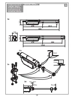
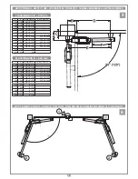
ing and closing positions (pos. 1, 2, 3, fig. 7).
It is the responsibility of the installer to make sure that the following public safety
conditions are satisfied:
1) Ensure that the gate operating installation is far enough away from the main
road to eliminate possible traffic disruptions.
2) The ram must be installed on the inside of the property and not on the public
side of the gate. The gates must not swing outwards onto a public area.
3) The ram is designed for use on gates through which vehicles are passing.
Pedestrians should use a separate entrance.
4) The gate must be in full view when it is operating therefore controls must be
situated in a position where the operator can see the gate at all times.
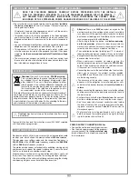
5) At least two warning signs (similar to the example on the right) should be
placed, where they can be easily seen by the public, in the area of the system
of automatic operation. One inside the property and one on the public side of
the installation. These signs must be indelible and not hidden by any objects
(such as tree branches, decorative fencing etc.).
6) Make sure that the end-user is aware that children and/or
pets must not be allowed to play within the area of a gate
installation. If possible include this in the warning signs.
7) Whenever a fully open gate leaf comes within
at least 500
mm
of a fixed structure the space must be protected by
an anticrush buffer.
8) A correct earth connection is fundamental in order to guar-
antee the electrical safety of the machine
9) If you have any questions about the safety of the gate operating system, do not
install the ram. Contact your dealer for assistance.
TECHNICAL DESCRIPTION
200/BLA24S
Self-locking electromechanical
24 Vdc
ram suitable for hinged
gates up to
3 m
in length and
150 kg
in weight (per gate leaf).
200/BLA24L
Self-locking electromechanical
24 Vdc
ram suitable for hinged
gates up to
4 m
in length and
300 kg
in weight per gate leaf (up to
5 m, 300
kg
addition of an electric locking device).
-
24 Vdc
motor with a steel never ending screw.
- External carter in extruded aluminium.
- Release mechanism components in shockproof plastic.
- Geared motor with steel gears enclosed in a die cast 2-piece aluminium
shell.
- Brackets and accessories in zinc-plated steel.
- Lubrication using permanently fluid grease.
ACCESSORIES
206/BLSTA
- Front and rear brackets.
206/BLASR
- Adjustable front and rear brackets.
980/XLSE11C
- Electric locking device
12 Vac
Attention!
Only for EU customers -
WEEE marking
.
This symbol indicates that once the products life-span has expired
it must be disposed of separately from other rubbish. The user
is therefore obliged to either take the product to a suitable dif-
ferential collection site for electronic and electrical goods or to
send it back to the manufacturer if the intention is to replace it
with a new equivalent version of the same product.
Suitable differential collection, environmental friendly treatment and disposal
contributes to avoiding negative effects on the ambient and consequently
health as well as favouring the recycling of materials. Illicitly disposing of this
product by the owner is punishable by law and will be dealt with according
to the laws and standards of the individual member nation.
During the opening/closing manoeuvre check for correct operation and activate
the emergency stop button in case of danger.
During blackouts the gate can be released and manually manoeuvred using the
supplied release key (see manual release mechanism).
Periodically check the moving parts for wear and tear and grease if required,
paying particular attention to the never ending screw pos. 13 fig. 2, using
lubricants which maintain their friction levels unaltered throughout time and are
suitable for temperatures of
-20 to +70°C
.
In case of failure or operational anomalies switch off the power at the mains
do not attempt to repair the appliance yourself. Periodically check the correct
operation of all safety devices (photoelectric cells etc.).
Eventual repair work must be carried out by specialised personnel using original
spare parts. The appliance is not suitable for continuous operation and must be
adjusted according to the model (see technical data on page 20).
The minimum controls which may be installed are OPEN-STOP-CLOSE, these
controls must be installed in a location not accessible to children.
Before starting the installation of the system check that the structure which is
to be automated is in good working order and respects the local standards and
regulations in force.
To this end make sure that the gate is sufficiently rigid (if necessary reinforce the
structure) and that the runner guides slide easily.
You are advised to grease all the moving parts using lubricants which maintain
unaltered friction characteristics over a period of time and are suitable for tem-
peratures of
-20 to +70°C
.
• Check the safety measures between the fixed and moving parts:
- a minimum space of
30 mm
must always be left along the entire distance
between the gate and the support column measured throughout the entire
opening angle of the gate;
- make sure that the space between the bottom of the gate and the pave-
ment never exceeds
30 mm
throughout the entire opening angle of the gate.
• The surface of the gate must not feature openings which allow a person’s
hand or foot to pass through.
• Check the exact positioning of the pivots, and their good working order (the
upper and lower hinges/pivots must be aligned on the same axis).
• Work out the run of the cables according to the command and control devices
fitted and make sure the system conforms to the local standard and regulations
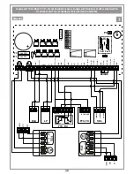
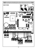
in force (see installation example fig. 1 pag. 2).
• Check that the appliance is suitable for the size, weight and duty cycle of the
gate to which it is to be applied (see duty cycle on page 20).
BLA24 INSTALLATION
Before reading the installation instructions, take note of the following basic concepts:
- the joint brackets (front and rear) must be mounted correctly at two different
heights;
- the brackets supplied can be welded directly to the structure or secured with
screws and screw anchors, provided the system is able to withstand the forces
imparted: by the actuator, by manual movement of the gate and (in certain condi-
tions) by the wind;
- the position of the brackets establishes the maximum opening angle and the
length of the actuator's linear stroke; consider that the longer the stroke of the
lead screw, the greater the torque and the smoother the movements of the gate
leaf; on the contrary, with a short stroke, movements may be more abrupt and
there will be less torque available. Tables "
1
" and "
2
" on page 6 show several
examples of bracket positions; the measurements are only guidelines and should
be used solely to prepare for installation.
APERTURA AUTOMATICA
NON AVVICINARSI
NON PERMETTERE A BAMBINI O AD
ANIMALI DOMESTICI DI SOSTARE NEL
RAGGIO D'AZIONE DEL CANCELLO
ATTENZIONE
IMPORTANT SAFETY INSTRUCTIONS
INSTALLATION INSTRUCTIONS
IMPORTANT REMARKS
IMPORTANT REMARKS
IMPORTANT REMARKS
READ THE FOLLOWING REMARKS CAREFULLY BEFORE PROCEEDING WITH THE INSTALLA-
TION. PAY PARTICULAR ATTENTION TO ALL THE PARAGRAPHS MARKED WITH THE SYMBOL
NOT READING THESE IMPORTANT INSTRUCTIONS COULD COMPROMISE THE CORRECT WORK-
ING ORDER OF THE SYSTEM AND CREATE DANGER SITUATIONS FOR THE USERS OF THE SYSTEM.
USER INSTRUCTIONS


