13
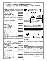
DISPLAY MENU
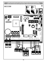
The segments regarding the command status
(
LED “ON”
=
command active
) and safety status
(
LED “ON”
=
safety device at rest
) light up.
The number of manoeuvres appears on the display.
This number always remains visible until you
change the setting. Once
999999
has been
exceeded the lighting up of the decimal point on
the display equals 1 m the six figure number.
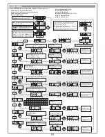
10 sec
PRESS PROG
10 sec
The status of the security devices
TB
,
FTCI, FTCS
and
CSP
are always shown on the display.
Memorising the DIP-SWITCH settings and displaying
the firmware version (“
01.
”)
PRESS
PROG
PRESS
PROG
PRESS
PROG
PRESS PROG
PRESS PROG
10 sec
10 s after the last
modification you will
automatically exit the mode
and the selected values will
be saved (eg. 4)
10 s after the last
modification you will
automatically exit the mode
and the selected values will
be saved (eg. 3)
10 sec
10 sec
PRESS PROG
Each time the button is pressed the
number increases (from 1 to 4).
APL
= Setting the limited opening space (gate1):
1 = 1/3 of the distance :
2 = half the distance
3 = 2/3 of the distance :
4 = the entire distance
SNS
= Setting the current sensor.
1 = motor consu 2 amps
2 = motor consu 3 amps
3 = motor consu 3,5 amps
In the "
test
" mode (activated when the motor has
stopped) it is possible to check the status of the
command and safety devices.
The warning lights will activate once, each time a
“
TA-TC-TAL-TD-TB-FTCI-FTCS-CSP
” command is
received. To return to the normal mode press the button
again “
test
” will appear, then wait for 10 seconds.
10 sec
10 sec
PRESS PROG
When the ("
TA-TC-TD-TAL-TB- FTCI-FTCS-CSP
")
inputs are activated the warning lights will light up.
PRESS PROG
Each time the button is pressed the
number increases (from 1 to 3).
10 sec
10 s after the last
modification you will
automatically exit the mode
and the selected values will
be saved (eg. 3)
10 sec
10 sec
10 sec
PRESS PROG
Each time the button is pressed
the setting changes.
Deceleration settings
1 = Minimum 3 = Maximum
2 = Medium
PRESS PROG
Each time the button is pressed
the number increases (from 1 to 3)
.
10 sec
10 s after the last
modification you will
automatically exit the mode
and the selected values will
be saved (eg. 3)
10 sec
Setting the delay between the gates
1 = minimum gate delay 3 = maximum gate delay
2 = medium gate delay
PRESS PROG
Each time the button is pressed the
number increases (from 1 to 3)
.
10 s after the last modification
you will automatically exit the
mode and the selected values
will be saved (eg. underground)
PRESS
PROG
PRESS
PROG
PRESS
PROG
Selecting the type of motor
BL2124 = operator arm
HL2524 = underground operator
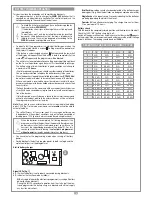
Selecting the type of security contact
0 1 2 3 4 5 6 7 8 9
TB
N.C. N.C. N.C. N.C. N.C. N.C. N.C. N.C. 8.2 KΩ 8.2 KΩ
FTCS
N.C. N.C. N.C. N.C. 8.2 KΩ 8.2 KΩ 8.2 KΩ 8.2 KΩ N.C. N.C.
FTCI
N.C. N.C. 8.2 KΩ 8.2 KΩ N.C. N.C. 8.2 KΩ 8.2 KΩ N.C. N.C.
CSP
N.C. 8.2 KΩ N.C. 8.2 KΩ N.C. 8.2 KΩ N.C. 8.2 KΩ N.C. 8.2 KΩ
For the values from A to F see the paragraph “contact selection” on page 16
10 sec
10 sec
PRESS PROG
Each time the button is
pressed the setting changes
(from 0 ... 9 - A ...F).
10 s after the last
modification you will
automatically exit the mode
and the selected values will
be saved (eg. 5)
PMT
= Motor power setting.
from level 1 (2.5A) to level 8 (6.0A)
PRESS
PROG
10 sec
10 sec
10 s after the last modification
you will automatically exit the
mode and the selected values
will be saved (eg. 3)
Parameters only present in CUSTOM motors
SPd
= Speed level during deceleration.
1 = minimum speed
3 = maximum speed
2 = medium speed
PRESS
PROG
10 sec
10 sec
10 s after the last modification
you will automatically exit the
mode and the selected values
will be saved (eg. 2)
Using the
PROG
button you can access the following functions in sequence:
- memorising the status of the dip-switches;
- display the status of the command and safety devices;
- display the number of manoeuvres;
- access the "
test
" mode;
- set the limited opening distance;
- set the current sensor level;
- selecting the type of motor;
- selecting the security contact
(N.C./8.2 kΩ);
- setting the deceleration time;
- setting the gate delay time.


