docs.carbide3d.com
05/01/20
v1.1
7
Connect the Communications Cable
Routing the Communications Cable
The communications cable has a MALE and a FEMALE connector. The male end of the cable connects to the
BitRunner (on the Y2-rail) and the female end connects into the Carbide Motion board (on the Y1-rail). The
cable can be routed across the machine one of two ways:
•
Directly under the machine.
•
Through the gap between the MDF baseplate
and the front OR rear endplate.
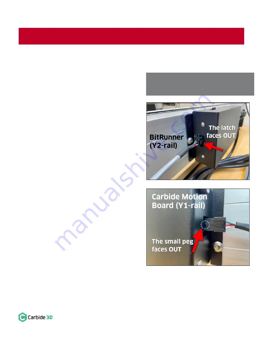
Connect the Male End to the BitRunner
The MALE end of the communications cable connects to
the front of the BitRunner on the Y2-rail. It has a plastic
latch on one side to secure it in place. Each of the six
prongs of the connector are molded to fit into the
BitRunner in only ONE WAY.
1.
Plug the male end of the cable into the BitRunner
with the plastic latch facing OUT (AWAY from the
Y2-rail). See
Figure 6
. Make sure the plug is fully
seated. You will hear the latch click into place.
Connect the Female End to the Carbide Motion Board
The FEMALE end of the communications cable connects
to the Carbide Motion board on the Y1-rail. There is a
small triangular-shaped peg on one side, towards the
end of the connector, which you can feel with your
fingers. Like the male end, this connector is molded to fit
into the Carbide Motion Board in only ONE WAY.
1.
Plug the female end of the cable into the
BitRunner connector protruding from the
Carbide Motion board, with the small triangular
peg facing OUT (AWAY from the Y1-Rail). See
Figure 7.
Press in and down to get the plug to
seat fully.
Figure 6
Figure 7
WARNING:
Use
CAUTION
when plugging in the communications cable. The connectors are polarized and MUST be
inserted properly. Failure to do so, will ruin both the Carbide Motion board and the BitRunner.
NOTE:
Avoid kinking the cable and ensure it will not
be snagged or pinched by any moving parts. Bundle
any excess cable and secure with a cable tie.


