background image


[email protected] 

docs.carbide3d.com


05/01/20  

v1.1


Both options require the removal of the Carbide Motion board enclosure from the Y1-rail and the removal of 
the Carbide Motion board from the enclosure.  

Carbide Motion Board Removal 

1.


Turn off and unplug your Shapeoko. 

2.


Disconnect the USB and power cables from the Carbide Motion board (located on the Y1-rail). 

3.


Remove the cover from the 

Carbide Motion board’s 

enclosure and disconnect the three (3) 

homing/proximity switch cables and four (4) stepper motor extension cables. 

4.


Use a 4mm hex key to remove the enclosure from the Y1-rail. 

5.


Use an SAE 

3

/

32

-inch hex key to remove the four (4) socket head cap screws in the corners of the 

Carbide Motion board. 

The Carbide Motion board is taped to the enclosure and will need to be gently pried away. 

6.


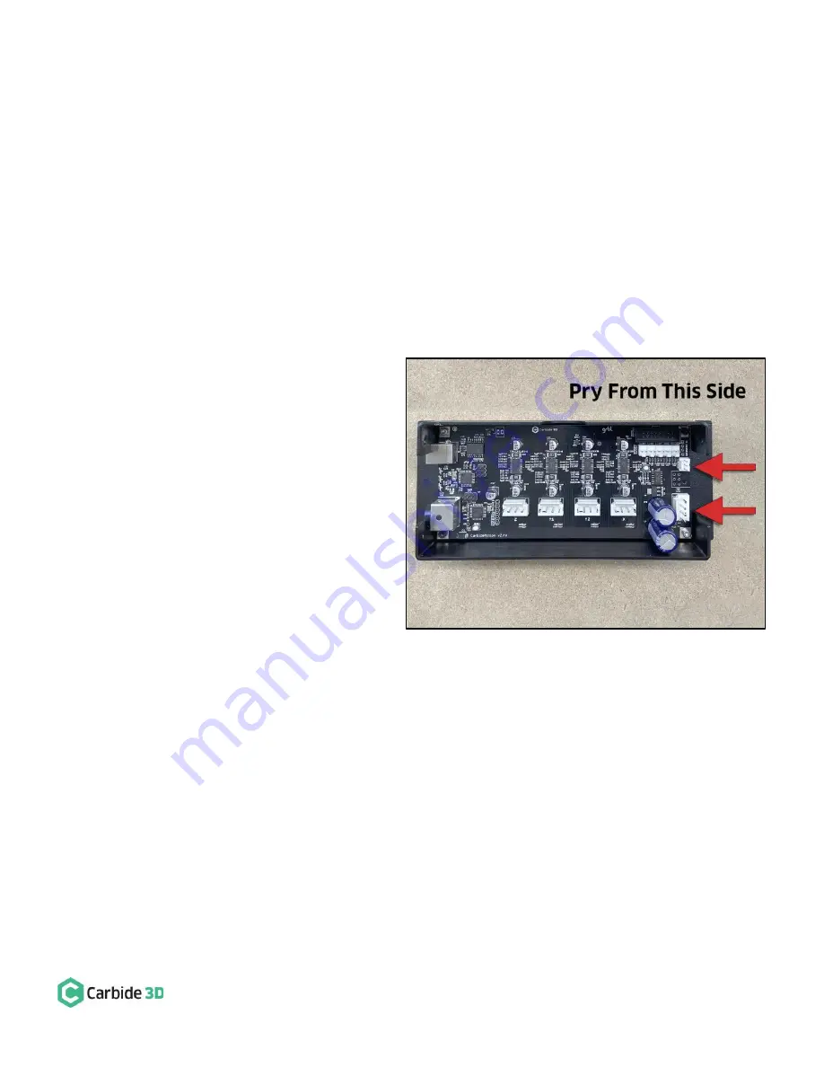
Gently pry the board away from the 
enclosure with your fingers. Pry from the 
FRONT end (opposite the USB and power 
ports) as shown in 

Figure 3

If you’re 

having trouble getting the board out, use 
an ESD flat head screwdriver or suitable 
implement to gently pry away. Do not 
remove the old thermal tape unless 
instructed to do so. 

Option 1: Carbide Motion Board 
Replacement 

Kit Option 1 includes a new Carbide Motion 
board with integrated BitRunner connector. 

To replace the Carbide Motion board: 

1.


Remove the old thermal tape from the enclosure’s aluminum heat

-sink. 

Figure 3 

Summary of Contents for BitRunner

Page 1: ...Kit Item Description Qty Note A BitRunner 1 BitRunner enclosure and attached power cords B Communications Cable 1 Gray 6 pin male to female extension cable C Mounting Hardware 2 M6 x 12mm button head...

Page 2: ...t carbide3d com and we will get you back on track Install the BitRunner Attach BitRunner to Y2 Rail Newer Models With Z Plus The BitRunner attaches to the two M6 holes on the outside of the Y2 rail wi...

Page 3: ...unting holes is 6 10 155mm 3 Use a 5mm drill bit for the tap hole and an M6 tap to form the threads Be sure to drill all the way through the outer wall of the extrusion and into the cavity 4 Use a 4mm...

Page 4: ...rail 5 Use an SAE 3 32 inch hex key to remove the four 4 socket head cap screws in the corners of the Carbide Motion board The Carbide Motion board is taped to the enclosure and will need to be gentl...

Page 5: ...board enclosure to the Y1 rail with the USB and power ports at the BACK and the 6 pin BitRunner connector at the FRONT 6 Reconnect the three 3 homing proximity switch cables and four 4 stepper motor e...

Page 6: ...e an SAE 3 32 inch hex key and the four 4 existing socket head cap screws to secure the modified Carbide Motion board to the enclosure 4 Use a 4mm hex key and two 2 M6x12mm button head cap screws to a...

Page 7: ...rom the Y2 rail See Figure 6 Make sure the plug is fully seated You will hear the latch click into place Connect the Female End to the Carbide Motion Board The FEMALE end of the communications cable c...

Page 8: ...1 Left Forward Auto On Off the LED is green or red The G code or absence thereof determines when BitRunner cuts or supplies power to the router If there is no G code nc file being executed in Carbide...

Page 9: ...d M6 Carbide Motion will pause the job cut power to the router and alert you that it s time to change the tool 2 For safety flip the power switch on the router to the OFF position and slide the power...

Reviews: