background image

9

step 4: installing anti-tip device

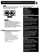
WARNING!

• All ranges can tip
• Injury to persons and 
property could result
• Install anti-tip device 
packed with range
• See installation instructions

Fig. 5

WARNING! 

RANGE TIPPING HAZARD!
1) All ranges can tip and injury can result.  
To prevent accidental tipping of the range, 
attach it to the floor, wall or cabinet by 
nstalling the Anti-Tip Device supplied.

2) A risk of tip-over may exist if the 
appliance is not installed in accordance 
with these instructions. 

3) If the range is pulled away from the wall 
for cleaning, service or any other reason, 
ensure that the Anti-Tip Device is properly 
reengaged when the range is pushed back 
against the wall.  

4) In the event of abnormal usage (such 
as a person standing, sitting, or leaning 
on an open door), failure to take this 
precaution can result in tipping of the 
range.  Personal injury might result 
from spilled hot liquids or from the 
range itself (Fig. 5).

READ THESE IMPORTANT 
SAFETY WARNINGS!

WARNING!

ELECTRICAL SHOCK HAZARD!
1) Use extreme caution when drilling 
holes into the wall or floor.  There may be 
concealed electrical wires located behind 
the wall or under the floor.

2) Identify the electrical circuits that 
could be affected by the installation 
of the Anti-Tip Device, then turn off 
power to these circuits. 

3) Failure to follow these instructions 
may result in electrical shock or other 
personal injury. 

CAUTION! 

PROPERTY DAMAGE!
• Contact a qualified installer or contractor 
to determine the proper method for drilling holes 
through the wall or floor material (such as 
ceramic tile, hardwood, marble, etc.).
• DO NOT slide range across unprotected floor.
• Failure to follow these instructions may result in 
damage to wall or floor coverings. 

NOTE:

The anti-tip device supplied with each range 
MUST be installed per these instruictions!  
failure to do so WILL void warranty. 

TOOLS NEEDED FOR INSTALLATION OF 
ANTI-TIP DEVICE!

1. Screwdriver, Phillips
2. Drill, electric or hand
3. Measuring tape or ruler
4. 1/8” drill bit (wood or metal wall or floor)
5. 3/16” carbide-tipped masonry drill bit 
(concrete or concrete block wall or floor)
6. 3/16” anchors, drywall, or concrete, 2 each 
(not required if mounting bracket is being 
attached to solid wood or metal. 
7. Hammer
8. Pencil or other marker

start here!

A.

Summary of Contents for PSGR24

Page 1: ...I N S TA L L AT I O N G U I D E P E R F O R M A N C E S E R I E S G A S R A N G E S THE POWER OF PERFORMANCE ...

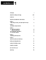
Page 2: ...ng the range 3 STEP 2 ventilation requirements 4 STEP 3 3a cabinet preparation 4 cabinet clearances 6 3b backguard installation 7 3c electrical supply 8 STEP 4 installing anti tip device 9 STEP 5 gas connection and hookup 11 testing and adjustments 13 caring for stainless steel 13 installer checklist 14 we re here for you 15 warranty 16 ...

Page 3: ...ide ourselves on superior customer service and work harder to respond to your needs quickly and effectively Our Customer Service representatives are here to assist you and are just a phone call away You can reach us toll free 1 866 402 4600 by e mail customerservice capital cooking com or by standard mail 13211 Florence Ave Santa Fe Springs CA 90670 When you contact us please make sure you have th...

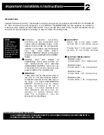
Page 4: ...e gas supply piping system by closing its individual manual shutoff valve during any pressure testing of the gas supply piping system at test pressures equal to or less than 1 2 psi 35 kpa DO NOT store or use gasoline or other flammable liquids or vaporous products in the vicinity of this appliance Smother flames with a close fitting lid or any metal tray Turn OFF the burner Be careful to prevent ...

Page 5: ...as Burning Appliances and C22 1 Canadian Electrical Code Part 1 PLEASE NOTE In the Commonwealth of Massachusetts gas connection must be performed by a licensed plumber or licensed gas fitter CAUTION When connecting the unit to propane gas make certain the propane tank is equipped with its own high pressure regulator in addition to the pressure regulator supplied with the range The pressure of the ...

Page 6: ...tal fire or burns ENSURE THAT THE RANGE IS COMPATIBLE WITH GAS SUPPLY AT THE INSTALLATION SITE BEFORE PROCEEDING FURTHER Return the unit to the dealer if it is not set for the proper gas supply available at the installation site IMPORTANT A back guard must be utilized when there is less than 12 horizontal clearance between combustible materials and the back edge of the range The Capital PERFORMANC...

Page 7: ...ing 4 Support the range uniformly across the bottom 5 Lift the range from the skid with a soft wheel dolly 6 Remove the angle mounting brackets from range This requires the installer to remove two screws holding each bracket then remove bracket and reinstall screws 7 Make sure gas and electric connections are made anti tip device is installed and the back guard installed prior to placing the range...

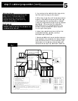
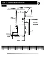
Page 8: ...ion will meet local requirements step 3a cabinet preparation 1 The range is a freestanding unit If the unit is to be placed adjacent to cabinets the clearances shown in Fig 1 are required The same clearances apply to island installations except for the overhead cabinets which must have a space wide enough to accept a suitable flared island hood as indicated in Fig 1 pg 5 2 The maximum depth of ove...

Page 9: ...with the National Fuel Gas code ANSI Z223 1 NFPA 54 We re here for you If you have any questions about this section please call us at 1 866 402 4600 and a Performance Series Customer Service Specialist will be glad to help answer any questions you may have DO NOT obstruct the flow of combustion and ventilation air to the unit IN OR INCH OOD IN AX FOR LEVEL COUNTER AX W 2ANGE EVELING LEGS FULLY EXT...

Page 10: ...I C 12 Min to Combustibles without backguard MODEL WIDTH A B C D E F G H I J PSGR24 23 7 8 25 43 1 4 27 3 8 38 5 8 44 1 2 58 1 2 1 5 16 28 1 4 6 36 1 2 PSGR30 29 7 8 25 43 1 4 27 3 8 38 5 8 44 1 2 58 1 2 1 5 16 28 1 4 6 36 1 2 PSGR36 35 7 8 25 43 1 4 27 3 8 38 5 8 44 1 2 58 1 2 1 5 16 28 1 4 6 36 1 2 PSGR48 47 7 8 25 43 1 4 27 3 8 38 5 8 44 1 2 58 1 2 1 5 16 28 1 4 6 36 1 2 ...

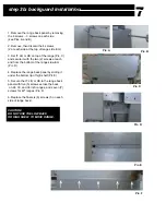
Page 11: ... with the two 2 screws at each end from the bottom of the range side trim Pic D 4 Replace the range back panel by sliding it under the bottom lip of high shelf Pic E 5 Secure the IT LB or HS to the range back panel with five 5 screws across the back on 24 30 and 36 inch ranges and seven 7 screws for 48 ranges Pic F 6 Replace the final six 6 screws 3 on each side of range back CAUTION DO NOT USE TH...

Page 12: ... the range Follow all governing codes and ordinances when grounding In the absence of codes follow the National Electrical Codes ANSI NFPA No 70 current issue GROUNDING METHOD The range is factory fitted with a power supply and cord with a three prong grounding plug It must be plugged into a matching grounding type receptacle connected to a correctly polarized 120 Volt circuit If the circuit does ...

Page 13: ...rilling holes into the wall or floor There may be concealed electrical wires located behind the wall or under the floor 2 Identify the electrical circuits that could be affected by the installation of the Anti Tip Device then turn off power to these circuits 3 Failure to follow these instructions may result in electrical shock or other personal injury CAUTION PROPERTY DAMAGE Contact a qualified in...

Page 14: ...OD OR METAL DRILL 1 8 PILOT HOLES FOR WALLS OR FLOORS COMPOSED OF DRYWALL SHEET ROCK OR OTHER SOFT MATERIALS DRILL 3 16 HOLES TO A MINIMUM OF 1 3 4 THEN TAP PLASTIC ANCHORS INTO EACH OF THE HOLES USING A HAMMER FOR WALLS OR FLOORS COMPOSED OF CONCRETE OR CONCRETE BLOCK DRILL 3 16 HOLES TO A MINIMUM DEPTH OF 1 3 4 THEN TAP CONCRETE ANCHORS INTO EACH OF THE HOLES USING A HAMMER FOR WALLS OR FLOORS H...

Page 15: ... with the manufacturer s instructions i Turn on gas and check supply line connections for leaks using a soap solution Do not use a flame of any sort to test for leaks START HERE Verify the type of gas being used at the installation site matches the gas type of the range As shipped from the factory units are configured for use with Natural Gas or Propane LP Make certain the range matches the type o...

Page 16: ...gas supply have been carefully checked for leaks and that the unit has been connected to the electrical power supply Turn the manual gas shut off valve to the open position Check the operation of the sealed gas burners and grill by pushing and turning each knob counterclockwise to HI The burner igniters will click until the flame ignites Burner flames should be BLUE and stable with no yellow tips ...

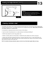
Page 17: ...gic DO NOT allow deposits to remain for long periods of time DO NOT use ordinary steel wool or steel brushes Small bits of steel may adhere to the surface causing rust DO NOT allow salt solutions disinfectants bleaches or cleaning compounds to remain in contact with stainless steel for extended periods of time Many of these compounds contain chemicals which could prove harmful Rinse with water aft...

Page 18: ...ut requiring removal of range c Unit tested and free of gas leaks c Gas supply pressure does not exceed 14 37 mb W C ELECTRICAL c Receptacle with correct over current protection is provided for service cord connection c Proper ground connection c Proper polarity at receptacle c Kick panel in place with all screws secure OPERATION c All internal packing materials removed Check below grates and gril...

Page 19: ...on ____________________ please make a notation for future reference A brief description of the problem____________________ please make a notation for future reference Dealer name____________________________________________________________________ Your satisfaction is of the utmost importance to us If a problem cannot be resolved to your satisfaction please write or fax us at Capital Cooking Equipm...

Page 20: ...ping damage Service by an unauthorized agency Damage or repairs due to service performed by an unauthorized service agency or the use of unauthorized parts Service during other than normal business hours Improper installation such as improper hook up Service visits to teach consumers how to use the appliance correct the installation reset circuit breakers or replace home fuses Repairs due to other...

Page 21: ...s Some product pictures may be shown with optional equipment Further information can be obtained from your authorized Capital Cooking Equipment dealer or visit us online at www capital cooking com 2006 Capital Cooking Equipment Inc Not to be reproduced wholly or in part without written permission from Capital Cooking Equipment Inc Capital Cooking Equipment Inc 13211 Florence Ave Santa Fe Springs C...

Reviews: