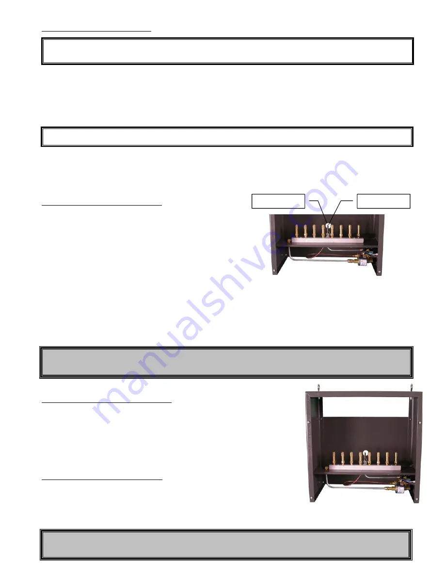
LIGHTING THE PILOT FLAME
1) Connect the power supply to the power connection on the side of the generator and plug it into the wall or your CO
2
controller.
2) Ensure the power switch on the side of the unit is OFF. Turn ON the gas supply to the unit.
3) There are (2) one inch holes in the center of the front and back of the unit that allow access to the pilot flame without
removing the front panel. Using an extended tip lighter, apply a flame to the tip of the pilot burner tube.
4) Press and hold down the red button on the pilot safety valve to allow gas flow to the pilot burner.
5) When the gas reaches the tip of the pilot burner, the pilot will light up. Continue to hold down the red button for up to a
minute until the thermocouple heats up. When it hot enough, the pilot will remain lit after releasing the red button.
6) Once the pilot flame is lit, turning the unit’s power switch ON will activate the main burner valve, allowing the main
burners to ignite.
OPERATING YOUR GENERATOR
1) Connect the CO
2
generator’s power supply to the controller that you are using. Normally, the generator is used only during
daylight hours. At the very least a time clock or photo-controller should be used to turn the generator on only during the
day to eliminate waste.
2) If you are using a controller, set the CO
2
level to the desired PPM and plug in the power supply.
3) Turning the power switch ON will activate the main burner solenoid valve allowing the burner to ignite.
4) The amber pilot light is on as long as the main burner is running. (See troubleshooting)
MAINTAINING YOUR GENERATOR
The GEN-2 has been designed for years of trouble-free service. The brass burners
have been chosen over steel because of their superior performance over long periods
of operation. The powder-coated enclosure can be cleaned with normal cleaners and
will not “fade” over time. However, if for any reason the generator is not performing
correctly, shut off the gas supply and turn the unit OFF. Simple problems can be
remedied by consulting the troubleshooting guide within these instructions.
FRONT BURNER ACCESS PANEL
The unit must operate with all of the panels in place. However, the front panel can
be removed when installing additional burners. Four screws are used to secure the
panel in place. Simply loosen the screws and lift the panel off the “keyholes” in order
to expose the burner assembly. Be sure to replace the cover prior to operating the GEN-2.
NOTE:
The pilot flame must be lit in order for the main burner to receive fuel. Once the pilot flame is lit, it will not need
to be re-lit unless the gas supply is interrupted.
WARNING
The outer enclosure gets hot while operating, especially at the top of the unit. Do not touch the generator until it is cool.
NOTE
:
If lighting the unit for the first time, it may take a couple of minutes or so for the gas to purge the hose.
WARNING
There are no user serviceable parts inside this generator. Do not attempt to service the GEN-2 gas components.
The recommended CO
2
level for optimum growth is between
1000 to 1500 PPM. Above that is usually considered wasteful.
Above 5000 PPM is considered dangerous to animals and humans.
Side effects of excessive CO
2
include headaches and drowsiness.
Use a PPM controller to ensure you are maintaining the proper PPM
level. Once your unit is set up, connected and the pilot flame is
lit… you’re ready to start up the generator.
Thermocouple
Pilot assembly


