background image

5

Specifications

–  13 –

*We reserve the right to change the specifications without prior notice.

5.2

Contents of Tool Bag

Model and Type

CM1802

Main Transmission

HST (Continuously Variable)

Auxiliary Transmission

Constant Mesh

Tires

Front AGR 3.50-7 / Rear 16 x 7.00-8

Steering

Rack and Pinion, Round Steering Wheel

Brake

Internally Expanding

Cutting Width

mm

900

Cutting Height

mm

0 - 75 (5 steps)

Blade Type

Free / Fixed Knife & Stepped Stay

Number of Blades

2

Blade Drive Train

Belt Drive

No.

Content

Quantity

Note

1

Operator's Manual

1

This manual

2

Operator's Manual for the Engine

1

3

Engine Service Tool

for servicing engine

Dr

iv

e

Tr

ain

Cutting

System

Summary of Contents for CM1802

Page 1: ...e attempting to operate maintain and inspect this machine Keep this manual with care so that it may be consulted in oper ating maintaining or inspecting this machine 5324 5201 000 CHIKUSUI CANYCOM INC 90 1 Fukumasu Yoshii machi Ukiha shi Fukuoka Japan 839 1396 Tel 81 0 943 75 2195 Fax 81 0 943 75 4396 ...

Page 2: ...ous Always follow the instructions in this manual when oper ating maintaining or inspecting machine This machine is a work vehicle for mowing Do not use it for other purposes Driving this machine on a public road or its equivalent may be illegal CHIKUSUI CANYCOM INC does not bear responsibility for accidents or violations of local regula tions Do not modify this machine Do not remove safety covers...

Page 3: ...ed in This Manual 2 1 4 Safety Labels 3 2 Warranty and After Sales Service 4 4 Controls and Components 10 5 Specifications 12 5 1 Product Specifications 12 5 2 Contents of Tool Bag 13 3 Safety 5 3 1 Safety Precautions 5 3 1 1 Training 5 3 1 2 Prepeartion 5 3 1 3 Operation 6 3 1 4 Servicing 8 ...

Page 4: ...ing and Oiling 35 7 5 1 Greasing 35 7 5 2 Oiling 36 7 6 Electrical System 37 7 6 1 Battery 37 6 Operation 14 6 1 Preparation 14 6 1 1 Checking and Filling Fuel 14 6 1 2 Inspecting and Filling Engine Oil 15 6 1 3 Inspecting and Filling HST Oil 15 6 2 Starting 16 6 3 Driving 20 6 4 Stopping 21 6 5 Parking 22 6 6 Transporting in Case of Emergency 22 6 7 Locking Differential 23 6 8 Adjusting Steering ...

Page 5: ...aning 39 7 7 1 Air Cleaner 39 7 7 2 Spark Plugs 40 7 7 3 Fuel Cock Fuel Filter 41 7 7 4 Blower Housing and Cooling Fan 42 7 8 Adjusting 43 7 8 1 Drive Belt 43 7 8 2 Rotary Drive Belt 43 7 8 3 Rotary Brake 43 7 8 4 Parking Brake 44 7 8 5 Drive Lever 44 7 8 6 Tires 44 7 9 Replacing 45 7 9 1 Oil Filter Cartridge 45 7 9 2 Hoses 45 7 9 3 Cutting Blades 45 7 10 After Use Care 47 ...

Page 6: ... the end of this manual Receive the guarantee certificate together with a receipt after you have received instructions for handling of this machine Appendix Instruction manual for engine Included in the tool bag Be sure to read it together with this manual ...

Page 7: ... chapter describes the general safety rules which the user must observe when operating and working 4 Controls and Components This chapter explains the names and functions of the component parts 5 Specifications This chapter describes the specifications of this machine It also describes the contents of the tool bag 6 Operation This chapter explains the preparations before operation operating proced...

Page 8: ...tes an extremely hazardous situation which will result in death or serious injury if the user does not follow appropriate instructions Indicates a potentially hazardous situation which could result in death or serious injury if the user does not follow appropriate instructions Indicates a potentially hazardous situation which could result in injury to the user or damage to the machine if the user ...

Page 9: ... are attached to this machine When warning labels have come off or become difficult to see order new ones from a dealer by the part numbers shown below labels and attach them 1 5234 5064 000 2 5321 5116 000 3 5321 5113 000 5 5305 5327 000 4 3667 5062 000 2 2 1 4 5 3 ...

Page 10: ...course of using the unit At such times please be prepared to report the product model and product s serial number shown in the model label as well as the names of the manu facturer and model of the engine installed For the names of the manufacturer and model of the engine installed refer to Chapter 5 Specifications in this manual Page 12 Location of model label Model label Availability of Spare Pa...

Page 11: ...machine Consult your local authority The operator is responsible for the accidents or hazards caused to other people or their property This machine has a riding capacity for one person only Do not carry passengers other than the operator Observe the weight limit of this machine 120kg Always keep in mind that care and concentration is required when working with ride on machines Loss of control on a...

Page 12: ... cause burns Do not operate the machine under the influence of alcohol or drugs Do not operate the machine when you are tired ill or not feeling well Always check for obstacles before operating on new terrain This includes overhead obstacles such as the branches of a tree Before starting the engine and moving the machine scan around your surroundings and make sure all persons and other vehicles ar...

Page 13: ...ose that you feel like you could tip over When driving up a slope proceed at a steady rate of speed and throttle position Never move the throttle lever the drive lever the drive pedal or the steering wheel sud denly If the engine stalls or loses traction during a climb and cannot make it to the top of the slope do not try to turn the machine around Carefully back down slowly straight down the slop...

Page 14: ...erve all the previous precautions for driving driving on a slope loading and driving with a load and dumping Whenever you park the machine apply the parking brake and stop the engine Remove the key whenever you leave the machine unattended to prevent unauthorized use or acci dental starting Gasoline is extremely flammable and can be explosive When parking the machine indoors make certain that the ...

Page 15: ...body away from any moving part especially the cooling fan and the belts at the side of the engine Do not touch the engine muffler or exhaust pipe while the engine is running or soon after it has stopped These areas will be very hot and can cause burns The engine must be shut off before checking or adding oil ...

Page 16: ...onents 10 Differential Lock Lever Drive Lever Throttle Lever Cutting Height Adjust Lever Rotary Clutch Lever Parking Brake Lock Lever Brake Pedal Aux Transmission Shift Lever Cutting Blade Shield Forward Backward Grass Outlet Head Lamp Switch Main Switch Choke Knob ...

Page 17: ...ake Pedal Stops machine When depressing brake pedal drive lever returns to neutral and machine stops Differential Lock Lever Use this lever when one side of the rear wheels is slipping When lever is pushed to ON differential lock is engaged When lever is OFF differential lock is released normal driving position During normal driving always put the lever to OFF position Head Lamp Switch Head lamp i...

Page 18: ...ront 800 Rear 735 Ground Clearance mm 105 Model FH541V Type 4 cycle air cooled V twin vertical shaft OHV gasoline Cylinder Bore x Stroke mm 2 74x68 Displacement cm3 cc 585 585 Maximum Output kW PS rpm 12 5 17 0 3600 Maximum Torque N m kgf m 40 3 4 11 Starting System Electric Fuel Automotive Unleaded Gasoline Fuel Tank Capacity L 11 Ignition Electronic ignition Spark Plug Champion RCJ8Y Battery Typ...

Page 19: ...Tires Front AGR 3 50 7 Rear 16 x 7 00 8 Steering Rack and Pinion Round Steering Wheel Brake Internally Expanding Cutting Width mm 900 Cutting Height mm 0 75 5 steps Blade Type Free Fixed Knife Stepped Stay Number of Blades 2 Blade Drive Train Belt Drive No Content Quantity Note 1 Operator s Manual 1 This manual 2 Operator s Manual for the Engine 1 3 Engine Service Tool 1 for servicing engine Drive...

Page 20: ...nd fill fuel Fuel to be used page 30 Fuel tank capacity page 30 When fuel gauge approaches E empty refuel as soon as possible When using machine on a slope make sure the fuel level is below upper limit on fuel fil ter 2 Close filler cap firmly after refueling N O T E 14 Operation 6 Operation Before reading this chapter be sure to read Safety in Chapter 3 pages 5 to 9 Concerning the operation and c...

Page 21: ...cified amount open oil tank cap and add HST oil Oil to be used page 30 Amount of HST oil To the Upper Limit line when oil is cool On the model with charge pump 1 Inspect the amount of HST oil in HST oil tank If it is less than the specified amount open oil tank cap and add HST oil Oil to be used page 30 Amount of HST oil Up to the check bolt when oil is cool HST Oil Tank Upper Limit 15 6 Operation...

Page 22: ...e lock lever 3 Make sure rotary clutch lever is in OFF position 4 Make sure cutting height adjust lever is in TRAVEL posi tion When rotary clutch lever is in ON position safety switch is engaged and engine will not start N O T E 16 Operation Do not overfill HST oil HST oil expands due to heat when in use and may overflow N O T E Brake pedal Parking brake lock lever Cutting height adjust lever Rota...

Page 23: ...ure drive lever is in Neutral position Intermediate speed Throttle lever 8 Move throttle lever in between High speed and Low speed 9 Release parking brake lock lever and depress brake pedal fully Drive lever Aux transmission shift lever Choke knob When brake pedal is not fully depressed safety switch engages and engine will not start N O T E ...

Page 24: ...ng starter motor repeatedly when engine is hard to start It may damage starter gear When an operator does not sit on seat safe ty switch engages and engine will not start Never turn main switch to START position while engine is running It will damage starter CAUTION N O T E 13 Engage parking brake lock lever and push brake pedal into the fully depressed position 18 Operation OFF Main switch START ...

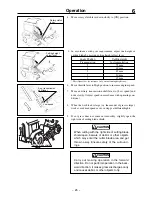
Page 25: ...new machine do not put an excessive load or avoid severe operations In some cold areas oil viscosity increases and normal operation may not be possible Continue warming up engine as indicated in the following chart N O T E 19 6 Operation Air temperature Recommended warming up time Over 0 C about 10 minutes 0 C to 10 C 10 to 20 minutes 10 C to 20 C 20 to 30 minutes Under 20 C more than 30 minutes C...

Page 26: ...ar Shifting 6 When shifting is needed stop and move auxiliary aux transmission shift lever to High or Low position Always stop machine to shift Shifting while travelling may damage transmission 20 Operation 6 3 Driving 1 Check the area around machine for safety 2 Release parking brake lock lever Parking brake lock lever Throttle lever High speed Low speed Aux transmission shift lever Drive lever F...

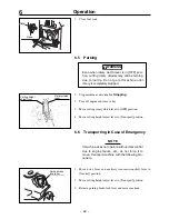
Page 27: ...tch to OFF position 5 Remove key Do not leave main switch in ON position Current from battery continues to flow and causes battery to discharge N O T E 6 Depress brake pedal fully and apply parking brake lock lever to lock brake pedal 21 6 Operation 6 4 Stopping 1 Move throttle lever to Low speed position to decrease engine speed Neutral OFF Main switch Brake pedal Parking brake lock lever Throttl...

Page 28: ...ht adjust lever to Transport position 6 6 Transporting in Case of Emergency If machine does not operate with normal control due to engine failure etc do not force it to move Transport machine with the following pro cedure N O T E 1 Move drive lever and auxiliary transmission shift lever to Neutral position 2 Move cutting helght adjust lever to Transport position 3 Release parking brake lock lever ...

Page 29: ...ion 6 8 Adjusting Steering Wheel 1 Release adjust knob and adjust the height of steering wheel by moving it up or down 2 Tighten knob after adjusting height 23 6 Operation 6 7 Locking Differential Rear wheels slippage on steep slopes or soft ground can be avoided by using differential lock lever Under normal driving condition always keep differential lock lever in OFF position N O T E Differential...

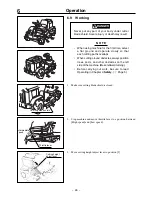
Page 30: ...evere injury or death may result When using machine for the first time select a flat ground and operate slowly so that each cutting paths overlaps When cutting around obstacles always position trees posts and other obstacles on the left side of the machine Make leftward turning Before carrying out work be sure to read Operating in Chapter 3 Safety Page 5 N O T E DANGER Cutting blade shield Interme...

Page 31: ...y slightly open the right side of cutting blade shield When cutting with the right side of cutting blade shield open beware of debris or other objects which may enter the cutter blade area and get thrown away Ensure safety of the surround ings Carry out mowing operation in the forward direction Do not perform operation in the back ward direction it makes grass discharge poorly and causes debris or...

Page 32: ...thly Thoroughly warm up engine and inspect exhaust gas and engine noise from idling to ful speed Look for exhaust gas leaks in exhaust pipes muffler etc Look for cracks or deformation on case loose lid or loose pipes Inspect air cleaner element and pre cleaner element Look for loose or missing bolts or nuts securing cylinder head or exhaust pipes This may be omitted if no exhaust or water leak is ...

Page 33: ...rt Check belt tension Valve clearance shall be as specified by factory Compression shall be as specified by factory Engine mount shall be free of cracks or defor mation Bolts and nuts shall not be missing and shall be fastened tightly Oil shall be at specified level and shall not be excessively dirty There shall not be any marked leak There shall not be any leak There shall not be any damage or de...

Page 34: ...d check looseness excessive play or miss ing cotter pin at joints Shall operate normally There shall not be any irregular noise or over heating Oil shall be at proper level Shall not be excessively dirty There shall not be any leak Can be shifted into each position positively Lever shall not be loose and there shall not be an excessive play Machine shall drive according to the opera tion of lever ...

Page 35: ...se or missing fasteners Blades shall be free of cracks or damage Carriage bolts shall be free of cracks damage or excessive wear Shield shall be free of cracks or damage skirt shall be free of cracks or damage and shall not be missing Shall be properly adjust ed Shall be free of damage or excessive wear Rotary shall stop imme diately Greasing points shall be sufficiently greased Head lamp shall li...

Page 36: ...ry 500 operating hours Every six months No need for lubrication for the first 6 months after purchase Every six months No need for greasing for the first 6 months after purchase Check every month and add as necessary Automotive Unleaded Gasoline API class SF or higher or SAE class 10W 30 Gear oil API class GL4 or 5 SAE class 80 SAE class 20W 50 engine oil or Mobile SHC629 Gear oil API class GL4 or...

Page 37: ...Z3096201010 53109906000 53139004000 53064301000 Check every 50 operating hours every week and replace if malfunctioning Check every 200 operating hours every month and replace if malfunctionin Replace if malfunctioning Replace if malfunctioning Replace if malfunctioning Replace if malfunctioning Every three years or when a malfunction is found Replace if malfunctioning Replace if malfunctioning Re...

Page 38: ...the condition of engine oil If it is dirty change it Oil to use page 30 Amount of engine oil Within the range A with oil gauge fully insert ed Do not exceed FULL 5 Re insert oil gauge 32 7 Maintenance 7 4 Fluids and Lubricants Insufficient or improper lubrication can not only cause machine to fail achieving smooth operation but also may cause it to break down and shorten its service life It is imp...

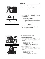
Page 39: ...e hole If oil level is low add oil Amount of oil page 30 Up to a point where oil reaches oil level check hole Adding 1 Remove filler plug 2 Fill the specified oil into the filler Oil to use page 30 33 7 Maintenance Changing 1 Prepare a suitable container to drain oil 2 Remove oil drain plug and drain oil from crankcase Hot oil can cause burns Properly dispose of drained oil N O T E CAUTION Oil lev...

Page 40: ... Check HST oil level when it is cold When it is hot HST oil expands and oil level goes up If an excessive amount of oil is put in oil may over flow when it reaches the operating temperature N O T E HST Oil Tank Check Bolt 34 7 Maintenance Changing 1 Prepare a suitable container to drain oil 2 Remove drain plug and drain oil Hot oil can cause burns CAUTION Properly dispose of drained oil 3 Replace ...

Page 41: ...se page 30 1 King pin Center pivot pin of front axle 2 Brake linkage 3 Rotary brake fulcrum 35 7 Maintenance 7 5 Greasing and Oiling Insufficient or improper oiling or greasing can cause seizure or rust It makes it difficult to achieve smooth operation N O T E 1 2 3 ...

Page 42: ...Fulcrum of auxiliary transmission shift lever 2 Rotary clutch lever fulcrum 3 Fulcrums on cutting height adjust linkage 4 Brake arm fulcrum 5 Drive lever fulcrum 6 Brake pedal fulcrum 7 Fulcrums on cutting blade shield also on the other side 7 36 Maintenance 6 7 2 7 3 5 3 4 1 7 ...

Page 43: ...aps Proper battery fluid level Between Upper limit and Lower limit Battery fluid Distilled water Charging Always remove battery from machine before charging Charging battery on machine may cause damages to electrical parts or wiring harness Connect cables to correct terminals on bat tery Connecting to wrong terminals will immediately blow fuse and damage battery and electrical system When disconne...

Page 44: ...ould be used only in emergencies After quick charging always recharge battery fully with regular charging Quick charging will shorten battery life severely N O T E 1 Remove battery 2 Connect a battery charger to battery Make sure to con nect cables to corresponding terminals Follow the instructions in the battery charger operation manual ...

Page 45: ...ment is markedly dirty or dam aged replace it 4 Install cover N O T E Replacing Inspect air cleaner elements every 50 hours every week Replace them if necessary 39 7 Maintenance 7 7 Cleaning 7 7 1 Air Cleaner Make sure to clean air cleaner elements on a regular basis every 50 hours of use Dirty air cleaner elements will badly affect engine performance power and life Air cleaner element is fragile ...

Page 46: ...cleaner 2 With sandpaper adjust spark gap as specified Standard spark gap 0 9 to 1 0 mm 3 Install spark plug 2 Remove spark plug with a plug wrench 3 Check plug for the following points and clean or replace it as necessary Specifications for spark plug Page 11 Breakage of insulator Worn electrode Carbon deposit Damage on gasket or thread Condition of insulator around electrode Degree of burning Da...

Page 47: ...free place Cleaning 1 Make sure fuel cock is closed N O T E 2 Remove filter pot o ring and fuel filter 3 Remove sediments dust water etc inside filter pot 41 7 Maintenance Fuel filter O ring Filter pot 4 Clean filter pot o ring and fuel filter in clean kerosene 5 Install fuel filter o ring and filter pot ...

Page 48: ... tank 2 Remove cover in front of fuel tank 3 Remove mounting bolts 4 pcs for fuel tank 4 Move fuel tank forward and keep it there 5 Remove blower housing mounting bolts and detach shroud 6 Inspect cooling fan blades for dirt or dust Clean them with compressed air CAUTION Fuel tank Mounting bolt Remove dirt or dust around these areas ...

Page 49: ...t holder and rotary drive belt between 3 and 5 mm when belt slips out of rotary check the clearance on belt holder at rotary side 43 7 Maintenance 7 8 Adjusting 7 8 1 Drive Belt Inspection 1 Visually check drive belt for damages If any damage is found replace drive belt 7 8 3 Rotary Brake Inspecting 1 Examine if rotary stops within 4 seconds after moving rotary clutch lever to OFF position If rota...

Page 50: ... while driving Remove seat move tension bolt at the foot of drive lever in direction of arrow and adjust lever movement 44 7 Maintenance 7 8 4 Parking Brake If play in brake pedal increases immediately make the following adjustment Poorly adjusted brake can cause a serious accident Adjust the play on brake pedal with adjust nut on brake wire so that the play is between 15 and 20 mm at the end CAUT...

Page 51: ... 1 Before installing new filter apply new oil on filter gasket 2 Follow instructions in operator s manual for the engine to install new filter 3 Remove oil gauge and fill new oil of specified grade 4 Check oil level 5 Start engine and check for leaks 7 9 3 Cutting Blades When handling cutting blade wear thick gloves or wrap blade with cloth Handle blades careful ly in order to prevent injuries 1 O...

Page 52: ...rriage bolt with new ones 5 Place collar and cap 6 Hold blade with strong stick like object 7 Thread nut B and tighten it to a specified torque Torque M12 44 1 53 9N m 450 50kgf cm 8 Thread nut A Tighten it by hand When it cannot be turned by hand tighten it for one turn by a wrench 9 Close cutting blade shield cover N O T E CAUTION 5324M 0709 020E Nut A Nut B Cap Collar Blade Direction of Rotatio...

Page 53: ...arts and cause rust to built up Cover machine with a water proof sheet when keep ing it outdoors In cold areas Remove all dirt water and foreign objects from machine Any remaining dirt may freeze and cause damages Place machine on a concrete floor dry firm ground or wooden blocks Cover machine with a water proof sheet when keep ing it outdoors If machine freezes and does not move do not force it t...

Page 54: ...lade clutch lever to ON position 6 Oil and grease areas to be oiled and greased Pages 35 and 36 7 Remove key from main switch 48 8 Storage 8 Storage When storing machine for a long time appropriate maintenance is required for future use After performing After Use Care page 47 follow the instructions below Do not store machine battery or fuel near open flame or in a high temperature area Doing so m...

Page 55: ...s about long term storage of engine N O T E 49 8 Storage 8 2 Battery 1 Remove battery from machine Page 37 When storing with battery in machine disconnect battery ground cable 2 Check battery fluid level and add fluid as necessary 3 Store battery in a dry cool place Although battery can keep its charge for about 6 months it is recommended that it be recharged before it completely dis charges for l...

Page 56: ...8 3 3 Engine Oil 1 Change engine oil Pages 32 50 8 Storage 8 3 2 Air Cleaner 1 Remove the cleaner element and thoroughly clean it Pages 39 Oil drain plug Paper element Cover Wing bolt Form element Hook ...

Page 57: ...OFF position Safety device is actuated Brake pedal is not depressed Safety device is working Battery is over discharged Battery cable is disconnected Fuse is blown Open circuit or contact failure of wiring Lack of fuel Air or water in fuel Excessive intake of fuel Engine oil level is wrong or wrong engine oil High oil vis cosity Poor ignition due to dirt on spark plug or poor sparking Insufficient...

Page 58: ...ing bolts Others Engine oil leak Insufficient engine oil Blower housing and cooling fin clogging Fuel leak from fuel system Clogged air cleaner Choke knob is pulled choke valve is closed Poor compression Clogged air cleaner Excessive oil intake Bad fuel Corrective action Open fuel cock Page 16 Fill Page 14 Fill Page 14 Check and add oil Page 32 Consult dealer Adjust Consult dealer Clean or replace...

Page 59: ... brake drum Water soaks inside of drum Worn out tire Incorrect adjustment Incorrect tire air pressure Insufficient greasing of king pin Malfunction inside steering gearbox Incorrect tie rod adjustment Incorrect tire air pressure adjustment Loose tire fixing bolt Breakage of wheel bearing Crack of tire Improper wiring Bulb is disconnected Blown fuse Corrective action After checking adjust oil level...

Page 60: ...rrective action Perform the operation when grass is dry Mow twice with a higher mowing height Set the mower to a higher mowing height Page 25 Set the mower to the maximum motor speed Work more slowly Work more slowly Set the mower to the maxi mum motor speed Check engine speed Mow twice Replace the blade with a new one Pages 45 and 46 Clean the internal surface of the rotary cover Set the mower to...

Page 61: ...of blade Low engine speed Operating speed too high Grass accumulating or coiling around blade or around shaft Corrective action Replace the blade with a new one or balance the blade properly Pages 45 and 46 Increase engine speed to a maximum value Check engine speed Slow down operating speed Clean up blade ...

Page 62: ... on them 2 Securely hook running boards to loading deck of truck so that there is no step in height between boards and truck s loading deck Transporting 56 Do not allow any one to come near machine truck and run ning board while loading or unloading machine Do not turn on the running boards Machine may drop off the running boards When moving up or down running boards drive machine slowly at low sp...

Page 63: ...rs TEL 81 0 943 75 2195 FAX 81 0 943 75 4396 Foreign Trade Center TEL 81 0 3 3552 6277 FAX 81 0 3 3552 6288 CHIKUSUI CANYCOM INC http www canycom co jp All rights reserved Unauthorized use or reproduction of this material is prohibited ...

Reviews: