background image

99

Menu Description

Ad
va

nc

ed

 G

u

ide

Menu Description

Submenu

Function

Black level 
adjustment

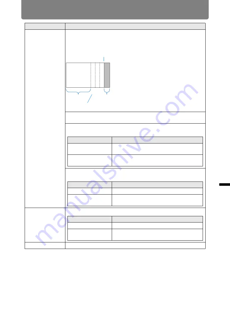
Because black is lighter in the blending area than in other areas, you can 
adjust the black level outside the blending area to make this difference in 
brightness less noticeable.

Off

Do not adjust the black level.

Area

Adjust areas C - A to smoothen the boundaries of the blending area.

Black level adjustment

Adjust the black level brightness and color of areas B and D.

Marker

Show the blending area markers.

Reset

Reset the marker settings.

CBA

Left image

Position of end 
marker (hidden)

Area D

Blending area

Areas C - A (default: 0)

Area A:  Black level cannot be adjusted.
Area B:  Adjust to a black level different 

from that of area D.

Area C:  Adjust to provide a smooth 

transition relative to the black 
levels of areas B and D.

Option

Function

Side

Select the direction to adjust from Left/Right/
Top/Bottom.

A-Width/ B-Width/ 
C-Width

Adjust the widths of areas A - C.

Option

Function

B/D-area base

Adjust the black level brightness of B/D areas.

B/D-area red / green / 
blue

Adjust the red, green, and blue components of 
B/D area black levels individually.

Option

Function

Off

Hide the blending area markers.

On

Show the blending area markers. The start 
marker is red, and the end marker is green.

Summary of Contents for WUX500ST

Page 1: ...ocedure Connection Procedure Projection Procedure Convenient Features Advanced Guide Using Menus Menu Configuration Menu Description Advanced Projection Other Information Maintenance Product Specifications Troubleshooting ENG MULTIMEDIA PROJECTOR User s Manual ...

Page 2: ...s manual thoroughly to make the most of your projector Installation of the projector should be performed by a qualified technician if possible Contact the Canon Customer Support Center for further information Symbols Used in This Manual Sections labeled with these symbols give the following kinds of information Indicates precautions and information to note when using the projector Symbols of Butto...

Page 3: ...ect an Input Signal 50 Step 3 Adjust the Image 51 Step 4 Select an Aspect Ratio Screen Aspect Matching the Screen 54 Step 5 Adjusting Keystone Distortion 58 Step 6 Select the Image Quality Image Mode 61 Step 7 Turn the Projector Off 62 Convenient Features 63 Advanced Guide 65 Using Menus 66 Menu Configuration 66 Basic Menu Operations 67 Menu Configuration 69 Menu Description 79 Input settings 79 I...

Page 4: ...oduct Specifications 179 Relationship between Aspect and Screen Aspect 179 Displayed Test Patterns 183 Supported Signal Types 184 Troubleshooting 192 LED Indicator Details 192 Symptoms and Solutions 193 Index 199 Option 201 ...

Page 5: ...vity standard HDBaseT offers a convenient connection for carrying high quality video and audio signals equivalent to HDMI across distances up to 100 m over a single LAN cable P44 P45 P107 P108 This terminal can also be used to connect the projector to a network P114 Zooming to the Fit Screen Size The size of projected images can be adjusted using digital zoom on the projector P95 Close Range Proje...

Page 6: ...ils on Networked Multi Projection NMPJ refer to the NMPJ user s manual Wi Fi Connectivity In addition to wired LAN connectivity the projector also supports Wi Fi In Projector Access Point PJ AP mode the projector can be connected to up to five computers without using a wireless access point A combination of wired or wireless connections to suit the installation environment enables projection from ...

Page 7: ...and try the solutions in the Troubleshooting section in the back of this manual If the problem still persists contact the Canon Customer Support Center CAUTION TO REDUCE THE RISK OF ELECTRIC SHOCK DO NOT REMOVE COVER OR BACK NO USER SERVICEABLE PARTS INSIDE EXCEPT LAMP REPLACEMENT REFER SERVICING TO QUALIFIED SERVICE PERSONNEL THIS SYMBOL INDICATES THAT DANGEROUS VOLTAGE CONSTITUTING A RISK OF ELE...

Page 8: ...aintained Do not cover the ventilation slots on the projector Heat build up can reduce the service life of your projector and can also be dangerous If the projector is unused for an extended time unplug the projector from the power outlet Do not project the same image for a long time An afterimage may remain on the LCD panels due to the characteristics of the panels of the projector CAUTION ON HAN...

Page 9: ...ojector on an unstable cart stand or table The projector may fall causing serious injury to a child or adult and serious damage to the projector Use only with a cart or stand recommended by the manufacturer or sold with the projector Wall or shelf mounting should be carried out in accordance with the manufacturer s directions and should use a mounting kit approved by the manufacturers An appliance...

Page 10: ...m the wall outlet and refer servicing to qualified service personnel under the following conditions a When the power cord or plug is damaged or frayed b If liquid has been spilled into the projector c If the projector has been exposed to rain or water d If the projector does not operate normally after following the operating instructions Adjust only those controls that are covered in the operating...

Page 11: ...to be disposed of with your household waste according to the WEEE Directive 2012 19 EU the Battery Directive 2006 66 EC and or national legislation implementing those Directives If a chemical symbol is printed beneath the symbol shown above in accordance with the Battery Directive this indicates that a heavy metal Hg Mercury Cd Cadmium Pb Lead is present in this battery or accumulator at a concent...

Page 12: ...rference to radio communications Operation of this equipment in a residential area is likely to cause harmful interference in which case the user will be required to correct the interference at his own expense The cable with a ferrite core provided with the projector must be used with this equipment in order to comply with Class A of the FCC Rules Use of a shielded cable is required to comply with...

Page 13: ...observed To ensure safe use always observe this information Denotes the risk of injury from improper handling if the information is not observed To ensure safe use always observe this information Denotes the risk of electric shock from improper handling if the information is not observed To ensure safe use always observe this information Denotes the risk of burns from improper handling if the info...

Page 14: ...ater or other liquid has entered the projector If metal or any other foreign material has entered the projector If the projector is knocked over or dropped and the cabinet is damaged Pay attention to the following points regarding the power source power plug and handling of the connector Failure to do so may cause a fire or electric shock Do not place any objects on the power cord and do not allow...

Page 15: ...e power plug or connector when removing Incorrect handling may damage the power cord Do not insert any metal objects into the contact parts of the power plug or connector Do not remove the power plug or connector with wet hands Insert the power plug and connector securely up to the base Additionally do not use a damaged power plug or an outlet that is loose When using an extension cord do not exce...

Page 16: ...ugged any other cables Unplug the projector before cleaning or maintenance Do not install the projector in a location that is damp or dusty or where there is a lot of oily smoke or steam Oil can degrade the plastic which could result in a ceiling mounted projector falling from its mounting Make sure to implement anti fall measures such as an anti fall wire when installing the projector in high pla...

Page 17: ...f children may approach the projector or touch it always ensure the projector is used under adult supervision Do not hold or install optical instruments such as magnifying glasses reflectors or glasses in the path of light from the projector If projected light is refracted or reflected and enters people s eyes it may result in eye injury When setting the projector on a high surface for projection ...

Page 18: ... for a while the lamp may have ruptured In this case never attempt to replace the lamp by yourself Always request service from a qualified technician or the Canon Customer Support Center With ceiling mounted projectors the lamp may fall out when you open the lamp cover or during replacement During replacement make sure no one is under the projector and stand to the side of the lamp cover not direc...

Page 19: ...jector or sit stand on it Pay particular attention to prevent small children from doing so The projector may be knocked over and this could result in damage or a personal injury Do not place the projector on an unstable or slanted surface Doing so may cause the projector to fall or be knocked over and could result in a personal injury Do not place any objects in front of the lens during projection...

Page 20: ...llows Environment of use 0 C 32 F to 40 C 104 F up to 85 RH Storage temperature 20 C 4 F to 60 C 140 F When using the projector at altitudes above 2 300 m 7 545 8 or when projecting upward or downward Adjust projector installation settings from the menu P96 Failure to adjust the settings may shorten the lamp life or damage the lamp Do not install the projector facing the wrong direction Install th...

Page 21: ...ith excessive temperature or humidity This may damage the projector Acceptable ranges for operating and storage temperature and humidity are as follows Operating temperature and humidity applies to when the projector is projecting or in standby mode Prepare the projector as described below before carrying it Disconnect the cables connected to the projector Carrying the projector with the cables at...

Page 22: ... until the condensation has evaporated for the image projected to return to normal At Altitudes above 2 300 m 7 545 8 Adjust the Settings Projector settings must be adjusted when using the projector at altitudes of 2 300 m 7 545 8 or higher Specifically refer to instructions for Fan mode P96 in the Install settings menu If the air intake or exhaust vent is blocked heat will accumulate inside the p...

Page 23: ...igh location it is necessary to periodically clean the air intake and exhaust vents and the area around the air filter Dust that accumulates in intake or exhaust vents may impair ventilation raising the temperature inside and posing a risk of damage or fire Use a vacuum cleaner or similar means to remove dust from the intake vent and exhaust vent ...

Page 24: ...7 in the Install settings menu Do not attempt to install the projector for upward or downward projection by yourself Always request installation by a qualified technician or the Canon Customer Support Center Failure to do so may damage the lamp Upward projection Inclination of the projector should be no more than 10 from the vertical axis Downward projection Inclination of the projector should be ...

Page 25: ...indows Windows Vista Windows 7 Windows 8 Windows 8 1 and Windows 10 are registered trademarks or trademarks of Microsoft Corporation in the United States and or other countries Mac Mac OS and Macintosh are trademarks of Apple Inc registered in the United States and or other countries HDMI the HDMI logo and High Definition Multimedia Interface are trademarks or registered trademarks of HDMI Licensi...

Page 26: ... STATED IN WRITING THE COPYRIGHT HOLDERS AND OR OTHER PARTIES PROVIDE THE PROGRAM AS IS WITHOUT WARRANTY OF ANY KIND EITHER EXPRESSED OR IMPLIED INCLUDING BUT NOT LIMITED TO THE IMPLIED WARRANTIES OF MERCHANTABILITY AND FITNESS FOR A PARTICULAR PURPOSE THE ENTIRE RISK AS TO THE QUALITY AND PERFORMANCE OF THE PROGRAM IS WITH YOU SHOULD THE PROGRAM PROVE DEFECTIVE YOU ASSUME THE COST OF ALL NECESSAR...

Page 27: ...o available RS RC05 However some buttons are not supported with this projector The RS RC05 can also be used as a wired remote P36 Computer cable 1 8 m 5 9 mini D sub 15 pin mini D sub 15 pin Power cord 1 8 m 5 9 For Continental Europe Warranty Card For the U S A and Canada Lens cap Important Information Always remove the cap before projection Accidentally leaving the cap on during projection may d...

Page 28: ... remote receiver P36 Air intake vent Air filter P173 Adjustable feet P38 Hole caps P39 Attach option feet sold separately Power cord connector P46 Terminals and connectors P32 Side control P29 LED indicators P30 Lamp cover Infrared remote receiver P36 Anti theft lock hole An anti theft wire cable not included can be connected Exhaust vent Do not block the air exhaust Doing so may cause a malfuncti...

Page 29: ...ly in accordance with the signal from a computer when the analog PC input is selected 4 KEYSTONE button P58 Corrects keystone distortion 5 Pointer VOL buttons P67 Up down left or right in menu navigation or other operations Adjust the sound volume VOL button Increases the volume VOL button Decreases the volume Selects the upper lower left or right item in the menu 6 OK button P67 Determines the it...

Page 30: ...ashing POWER ON green Lights up or flashes under normal conditions when the power is on WARNING red Lights up or flashes when an error occurs LAMP orange Lights up or flashes when a problem occurs with the lamp or lamp cover TEMP red Lights up or flashes when the internal temperature is high ...

Page 31: ...y every 4 seconds Waking from or entering standby mode blinks every second The time for replacing the lamp is near In standby mode The time for replacing the lamp is near During projection Internal temperature is high A lamp error has occurred A temperature error has occurred The lamp cover is open Another error has occurred A flashing LAMP indicator means that it is almost time to replace the lam...

Page 32: ... digital PC signal Digital PC A VGA DVI I cable can also be used to receive analog computer signals Analog PC 1 6 ANALOG PC 2 COMPONENT terminal COMPONENT P44 P45 Receives the analog PC signal Analog PC 2 A component cable can be used to receive the component image signal Component 7 HDMI terminal HDMI P44 P45 Receives digital video signals HDMI Carries both video and audio signals across a single...

Page 33: ... enables both horizontal vertical keystone correction by adjusting top bottom left right length and corner correction 5 D ZOOM button Zooms the image in or out digitally button Zooms the image in up to 12x button Zooms the image out 1x minimum buttons Move the zoom in location 6 IMAGE button P61 Switches the image mode image quality 7 GAMMA button P88 Adjusts the gamma of the image 8 INPUT button ...

Page 34: ...ected from the menu 14 EXIT button P68 Cancels functions such as menu display or test pattern during operation and returns to the image display 15 VOL button Adjusts the sound volume button Increases the volume button Decreases the volume 16 TEST PATTERN button P102 Displays the test pattern 17 MUTE button Mutes the sound 18 SPLIT button P161 Activates the split screen function 19 Fn button P112 C...

Page 35: ... attempt to recharge the batteries that are included with the remote control Remove the batteries when they are flat or when the remote control will not be used for a long period of time When replacing the batteries replace both at the same time Also do not use two batteries of a different type at the same time Insert the batteries with the and terminals in the correct directions If any liquid fro...

Page 36: ...remote receiver The remote control may be inoperative if there is an obstacle between the remote control and the projector or the infrared remote receiver on the projector is exposed to direct sunlight or strong light of lighting equipment When you use 2 or more projectors at the same time you can change the channel settings to prevent the 2 remote controls from interfering with each other P106 In...

Page 37: ...Installation Procedure Connection Procedure Projection Procedure Convenient Features Advanced Guide Using Menus Menu Configuration Menu Description Advanced Projection Other Information Maintenance Product Specifications Troubleshooting Basic Guide ...

Page 38: ...p between Projecting Distance and Image Size P41 On some screens colors may appear distorted when images are viewed from the side but this does not indicate a problem with the projector For best results use a matte screen with a wide viewing angle To avoid keystone distortion install the projector so that it is at right angles to the screen The screen must not be exposed to direct sunlight or ligh...

Page 39: ...In this case attach the option feet on top of the projector Attaching Option Feet RS FT01 Sold Separately Remove the hole caps and screw the option feet into the holes The caps are located at four positions on top of the projector They are removed differently depending on their position Removing hole caps labeled 1 Pry off the caps by inserting a slender tool such as a flat screwdriver in the depr...

Page 40: ...h the adjustable feet When changing the projection position with adjustable feet you can make the projector more stable by attaching option feet to the two holes toward the back of the bottom surface Hole cap Ceiling mounting Rear projection Mounting the Projector on the Ceiling You can mount the projector on the ceiling The ceiling attachment part No RS CL16 is required in order to mount the proj...

Page 41: ...down left or right For instructions refer to Adjusting the Image Position P53 Amount of Lens Shift The amount of lens shift is indicated as a percentage relative to the image height and width The lens shift ranges for the projector are as follows Image Size Dia 16 10 16 9 4 3 30 0 35 1 1 0 36 1 2 0 40 1 3 40 0 47 1 5 0 49 1 6 0 54 1 8 50 0 60 2 0 0 61 2 0 0 68 2 2 60 0 72 2 4 0 74 2 4 0 81 2 7 80 ...

Page 42: ...7 75 29 5 18 7 1 91 35 8 16 6 3 100 101 39 8 22 8 7 93 36 6 22 8 7 114 44 9 20 7 9 150 151 59 4 32 12 6 140 55 1 33 13 0 171 67 3 30 11 8 200 202 79 5 43 16 9 187 73 6 44 17 3 229 90 2 41 16 1 250 252 99 2 54 21 3 233 91 7 55 21 7 286 112 6 51 20 1 300 303 119 3 65 25 6 280 110 2 66 26 0 343 135 0 61 24 0 A values are the approximate vertical lens shift distance from the lowest image position B va...

Page 43: ...e other equipment Amplified speakers Mini jack RCA terminal Audio cable not included AUDIO OUT terminal ANALOG PC 1 DVI I terminal AUDIO IN 1 terminal Audio cable not included DVI I D Sub cable not included DVI I cable not included AUDIO output terminal Monitor output terminal Mini D sub 15 pin Monitor output terminal DVI terminal Computer Audio cable not included ...

Page 44: ...t included Computer cable not included or BNC cable not included Mini D sub 15 pin BNC terminal converter cable not included HDBaseT terminal HDMI terminal AUDIO IN 2 terminal ANALOG PC 2 COMPONENT terminal LAN cable CAT5e or better shielded not included HDBaseT transmitter HDMI cable not included HDMI cable not included HDMI terminal Computer ...

Page 45: ...uded Audio cable not included D terminal plug RCA plug component conversion cable not included RCA plug RCA plug component cable not included Component cable not included HDBaseT terminal HDMI terminal AUDIO IN 2 terminal ANALOG PC 2 COMPONENT terminal AUDIO OUT terminal LAN cable CAT5e or better shielded not included HDBaseT transmitter HDMI terminal AV equipment HDMI cable not included HDMI cabl...

Page 46: ...market is not guaranteed Some HDBaseT transmitters may not enable correct projection when used to connect source equipment to the projector Be sure to connect the ground wire of the power cord to ground Be sure to connect the ground wire before connecting the power plug to the outlet Also when you disconnect the ground wire be sure to unplug the power plug from the outlet beforehand Fully insert t...

Page 47: ...artup A window appears when the projector is turned on for the first time You can select a language to be used by the projector for displaying menus and messages in the window Select the desired language with the pointer buttons and press the OK button P48 You can change the language from the menu at a later time P110 Remote control Projector Changing Operations When Projector is Turned On You can...

Page 48: ...s Not Appear Set your notebook computer to output signals to an external monitor For more details refer to Changing Notebook Computer Screen Output P49 Adjusting Image Set the display resolution of the computer to the highest resolution or the resolution closest to that setting P51 Use the auto PC function to adjust shift in computer image or the flickering of the screen P52 Adjust the size of pro...

Page 49: ...ia keyboard operation To turn on the external monitor output with most computers press the function key F1 to F12 which is marked with the external monitor icon while holding down the Fn key The function key you use and the method used to turn on the external monitor output vary depending on the model For details see the manual for your notebook computer With Windows 10 Windows 8 1 Windows 8 or Wi...

Page 50: ...splayed in white and unavailable signal names are grayed out However Digital PC and Analog PC 1 may be grayed out even when available 2 You can switch the available input signal types by pressing the INPUT button You can select the target input signal with 3 Press the OK button to confirm the input signal type Screens of computers connected to the projector over a network can be projected when you...

Page 51: ...closest to the maximum output signal resolution of the projector 3 Click the OK button Windows 8 1 Windows 8 1 Move the cursor toward the upper or lower right corner to access the menu 2 Click Settings and then click Control Panel 3 From Control Panel Home Appearance and Personalization select Adjust screen resolution 4 Click the Resolution tab and move the slider to select the resolution closest ...

Page 52: ...display is shifted or there is flickering of the screen when Analog PC 1 or Analog PC 2 is selected press the AUTO PC button to adjust the projector to the optimal condition The adjustment results will be stored If the projector is used again with the same computer when the input signal is selected the image will be projected automatically under the same conditions that were previously adjusted If...

Page 53: ... the focus Instead of adjusting where the image is projected you can also move the image itself For details refer to Digital image shift P96 You can fine tune the image position by turning the upper part of the upper lens shift dial or the lower part of the lower lens shift dial Focus adjustment Focus ring 1 Turning upper lens shift dial clockwise Moves the image up 2 Turning upper lens shift dial...

Page 54: ... setting depending on the resolution of the computer or other AV equipment connected If the image is not projected with the desired aspect ratio refer to Relationship between Aspect and Screen Aspect P179 Selecting Screen Aspect Select the correct aspect ratio for the screen which is used 1 Press the MENU button to display the menu window 2 Press the buttons to select the Install settings tab Scre...

Page 55: ...10 Also select this screen aspect when projecting on a wall You can correct keystone distortion with this mode P58 16 9 Select this when you use a screen with an aspect ratio of 16 9 You can correct keystone distortion with this mode P58 4 3 Select this when you use a screen with an aspect ratio of 4 3 You can correct keystone distortion with this mode P58 Remote control Projector Remote control P...

Page 56: ...rojected at the aspect ratio of the input signal Select this mode for normal image projection 16 10 The image is projected using an input signal aspect ratio of 16 10 Select this if an image of 16 10 aspect ratio cannot be correctly projected in Auto mode 16 9 The image is projected using an input signal aspect ratio of 16 9 Select this if an image of 16 9 aspect ratio cannot be correctly projecte...

Page 57: ...appropriate aspect ratio Press the ASPECT button to change the aspect ratio type For more details about aspect ratios refer to Relationship between Aspect and Screen Aspect on page 179 You can also select any aspect ratio from Aspect in the menu P80 Some aspect ratios may not appear depending on the type of input signal Example Remote control ...

Page 58: ...te control or projector to display the horizontal vertical keystone adjustment window When Keystone is set to Horizontal vertical keystone Keystone correction may not be effective in some lens shift positions If keystone distortion is excessive and cannot be fully corrected straighten the projector so that it faces the screen directly Signals are processed digitally when keystone distortion is cor...

Page 59: ...ton Corner Adjustment 1 Press the KEYSTONE button on the remote control or projector to display the corner adjustment window To correct top distortion press the button To correct bottom distortion press the button To correct distortion on the right press the button Screen To correct distortion on the left press the button Remote control Projector Remote control Projector ...

Page 60: ...ustment Horizontal vertical keystone and corner adjustment can be reset as follows First press the KEYSTONE button on the remote control twice to display the Keystone reset window Next select OK with the button and then press the OK button Your specified keystone adjustment is now reset Corner adjustment settings will be cleared if you subsequently use Zoom P95 in the Install settings menu Remote ...

Page 61: ...e input set to Auto Image mode Compatible input signals Digital PC Analog PC 1 2 HDMI 1 HDBaseT 2 LAN USB Component HDMI 3 HDBaseT 4 Standard 1 Bright 2 Computer screens or media played with video software 3 Whites and natural colors Presentation 1 Bright 2 Images mainly consisting of text 3 Keeps the screen bright Dynamic 1 Bright 2 Media played with video software 3 Keeps the screen bright Photo...

Page 62: ...window shown below 2 When this window is displayed press the POWER button again to turn off the power After you turn the power off the projector will enter standby mode once it cools down If you want to continue projecting without turning off the power press a button other than POWER or else wait until the confirmation message disappears After turning off the projector wait at least 5 minutes befo...

Page 63: ... blacked out Freezing the Picture Projection can be temporarily frozen during computer operations that would be distracting or to pause playback of video or animation Press the FREEZE button to freeze the moving image The projector shows the following icon Press the FREEZE button again to return to the original display It is also cancelled when the input signal is terminated Projecting Images Stor...

Page 64: ... Adjust lamp and fan power consumption in the image mode Power management mode P108 Automatically turns off the lamp or the power after a certain period if the projector is idle without an input signal Power management duration P109 Specify the period after which the lamp or the projector should go off automatically if left idle without an input signal when Power management mode is set to Lamp off...

Page 65: ...stallation Procedure Connection Procedure Projection Procedure Convenient Features Advanced Guide Using Menus Menu Configuration Menu Description Advanced Projection Other Information Maintenance Product Specifications Troubleshooting Advanced Guide ...

Page 66: ...images input Image adjustment tab P86 You can adjust the image quality and colors according to your preference Install settings tab P93 This setting is used when installing the projector System settings tab P103 You can set the operation of the projector Network settings tab P120 These settings are for when using the projector from a PC via a network Information tab P151 You can check information ...

Page 67: ...tion to the top 3 Press the buttons to select an item 4 Select contents How to select the contents varies depending on the item Selecting from a list Example Aspect P80 Remote control Projector Remote control Projector Remote control Projector 1 Select Aspect 2 Press the OK button or button to display a list of the contents 3 Use the buttons to select the desired contents 4 When you have found the...

Page 68: ...o disappear The menu screen will also disappear if the EXIT button is pressed 1 Select Contrast 2 Use the buttons to adjust the setting 1 Select Menu position 2 Press the OK button to display a different screen 3 Then follow the instruction on the screen 1 Select Input signal settings 2 Press the OK button to display a different screen 3 Select Tracking 4 Use the buttons to select the setting then...

Page 69: ...ect Analog PC 1 2 P80 640 x 480 1920 x 1200 Input signal settings Analog PC 1 2 P81 Total dots Tracking Horizontal position Vertical position Horizontal pixels Vertical pixels Input level HDMI HDBaseT P82 Auto Normal Expanded Color space HDMI HDBaseT P82 Auto RGB YCbCr Over scan 1 HDMI HDBaseT P82 Off On Progressive Component HDMI HDBaseT P83 Off Film auto Video 1 Video 2 25p 30p PsF Factory defau...

Page 70: ...Destination projector setting IP address Enter Slideshow interval Animation effect Off Cross fade Fade out in Split screen Digital PC Analog PC 1 2 HDMI Component HDBaseT LAN USB P85 Off On Settings Split screen Off On Control rights Left screen Right screen Swap right left Yes No Layout Mode 3 7 Mode 5 5 Mode 7 3 Image priority in split screen mode COMMON P86 Primary Secondary Factory default or ...

Page 71: ...age mode Displayed when image mode 1 5 is selected P87 Brightness P88 Contrast P88 Sharpness P88 Gamma P88 Color adjustment Color level P88 Color balance Color temperature R Gain G Gain B Gain R Offset G Offset B Offset Advanced adjustment P89 Ambient light Off P89 Adjust Type Tungsten Fluorescent Level L H Factory default or state after Factory defaults is executed Under the following setting dif...

Page 72: ...Adjust Hue Saturation Brightness Reset Fine Tune Gamma P91 Lamp mode Full power P92 Power saver Reset P92 Positional lock Off P94 On Image flip H V None P94 Ceiling mounted Rear Rear Ceiling mounted Factory default or state after Factory defaults is executed Under the following setting differs from factory defaults 1 Analog PC 1 2 Digital PC HDMI when HDMI In is Computer Off Component HDMI when HD...

Page 73: ...istration Off P96 Adjust Fan mode Normal P96 High altitude Vertical projection Off P97 Upward Downward Edge blending Off P97 Adjust Side Color blending adjustment Black level adjustment Marker Reset Corner adjustment Screen color Normal P100 Greenboard Adjust Red Green Blue On screen P100 Menu position Upper L P101 Upper R Center Lower L Lower R Guide Off P101 On Show input status Off P101 On Over...

Page 74: ...P104 Logo position Upper L P104 Upper R Center Lower L Lower R No signal screen Black P104 Blue User logo Screen when blank Black P104 Blue User logo Projector on Skip P105 Canon logo User logo Interface settings P105 Key repeat Off P105 On Key lock Off P105 Main unit Remote wireless Remote control channel Ch1 4 P106 Independent Audio in terminal select P106 HDMI Off Audio in 1 Audio in 2 HDMI Fac...

Page 75: ... HDBaseT LAN Off Audio in 1 Audio in 2 LAN USB Off Audio in 1 Audio in 2 HDBaseT Off P107 On Image signal quality Communication settings Serial communication P107 Service port HDBaseT Detail Baud rate Data bits Parity Stop bit 1 2 Wired network LAN port HDBaseT HDMI image input Auto Computer HDBaseT image input Auto Computer Power management mode Disabled P108 Lamp off Standby Factory default or s...

Page 76: ...e Simplified Russian Chinese Traditional Dutch Korean Finnish Japanese Norwegian Other settings P111 Password settings Off P111 On Register password Password input P112 Fn button settings Disable P112 Split screen Gamma restore Off P112 Adjust Lamp counter Reset Return P112 Air filter counter Reset Return P113 Power counter P113 Firmware Yes No P113 Factory defaults OK Cancel P113 Network settings...

Page 77: ...wired P123 IP address Gateway address MAC address DHCP Off On TCP IP settings IP address Subnet mask Gateway address Apply Network setting initialization Yes No Detailed settings wireless P125 Mode SSID Security Channel Signal strength IP address Gateway address MAC address WiFi Protected Setup PBC PIN Manual settings Mode SSID Security Channel Key ID Key type Key Connect Factory default or state ...

Page 78: ...ime IP address IP address wired IP address wireless Projector name Comments System information ID The following settings are not reset even when factory defaults are restored Input selection Lamp counter Language Remote control channel Network settings Air filter counter Micro digital image shift Registration Fan mode Vertical projection HDBaseT Serial communication Wired network Create profile Ga...

Page 79: ... settings P81 Input level Select the input level for HDMI or HDBaseT signals P82 Color space Select the color space for HDMI or HDBaseT signals P82 Over scan Trim peripheral distortion from HDMI or HDBaseT images before projection P82 Progressive Select progressive processing for still images in cinematic content or moving images in videos P83 Slideshow interval Specify how long individual images ...

Page 80: ...using an input signal aspect ratio of 4 3 Zoom This cuts the upper lower or left right part of the screen according to the screen aspect and zooms in or out of the center of the image True size The image is projected with the original resolution of the input signal For LAN and USB input Auto is selected automatically Different contents are displayed for different screen aspects or input signal typ...

Page 81: ...Adjusts the tracking when the image distorts or flickers Horizontal position Adjust the horizontal image position to correct horizontal misalignment Vertical position Adjust the vertical image position to correct vertical misalignment Horizontal pixels Adjust the horizontal image resolution Vertical pixels Adjust the vertical image resolution Perform this adjustment if the Auto PC function P80 or ...

Page 82: ...itters may not support this If your AV equipment HDMI output can be set to Normal or Expanded we recommend Expanded The contrast of images will be improved and dark scenes will be rendered more realistically In this case set Input Level to Auto or Expanded For more detailed information refer to the user s manual for the AV equipment connected to the projector Option Function Auto Selects the optim...

Page 83: ...content Video 1 Suitable for projecting video with high image quality and relatively slow movement Performs progressive processing optimized for HD video Video 2 Suitable for projecting video with faster movement Performs progressive processing optimized for fast moving video 25p 30p PsF Performs progressive processing optimized for 1080 Psf 25 or 1080 Psf 30 video 25 or 30 fps respectively Select...

Page 84: ... Option Function Total number Specify the total number of projectors including all Master and Slave projectors 2 9 projectors can be specified Layout pattern Select a layout pattern Images from the Master projector are streamed to the upper left in the layout pattern Destination projector setting Specify IP addresses of projectors set to Slave mode Option Function IP address Enter the IP address o...

Page 85: ...d USB input cannot be combined for split screen display Similarly HDBaseT and HDMI input cannot be combined Control can be switched to the other side by pressing the on the remote control when or is displayed in the center of the image area When you switch to split screen display the left and right signals and input status are shown in the input window If the projector is turned off and then on ag...

Page 86: ...Create profile Save desired image quality settings as profiles P87 Baseline image mode Shows the image mode that is basis of the profile P87 Brightness Adjust image brightness P88 Contrast Adjust image contrast P88 Sharpness Adjust image sharpness P88 Gamma Correct loss of detail in shadows or highlights P88 Color adjustment Fine tune image colors P88 Advanced adjustment Fine tune noise reduction ...

Page 87: ... stored for your selected image quality settings Stored profiles are available in this setting as an image mode You can adjust the image quality by adjusting the following items in each image mode Brightness Contrast Sharpness Gamma Color adjustment Advanced adjustment and Lamp mode The saved settings consist of the brightness contrast sharpness gamma color adjustment advanced adjustment and lamp ...

Page 88: ...cted by pressing the GAMMA button on the remote control Color adjustment Image adjustment Color adjustment Adjust color related settings such as color level color balance and color temperature For more detailed adjustment use Fine Tune Gamma P91 Submenu Function Color level Adjusts the intensity of colors Color balance Adjusts the color balance of a purplish or greenish image Color temperature Adj...

Page 89: ...e Level L For an ordinary brightness of ambient light H For bright ambient light Random noise reduction Reduce random image noise Effective on noise with an irregular frequency or amplitude Option Function Off Disables random noise reduction Weak Middle Strong Specify one of three levels of intensity of the random noise reduction Examples of Ambient Light Level Settings Level Example Location L Pr...

Page 90: ...y of the mosquito noise reduction Dynamic gamma You can adjust the gradation representation of light and dark portions of an image automatically Option Function Off Disable dynamic gamma adjustment Weak Middle Strong Specify one of three levels of dynamic gamma adjustment Mem color correct Enhances skin tones blue skies and greens so that these colors are more consistent with people s remembered i...

Page 91: ...a curves Red green and blue can be adjusted separately Adjustments to white are also applied to the three other colors Note that adjusting any color will overwrite previous adjustments Adjustment is not applied to the projected menu itself For details on gamma correction see Gamma P88 Use input signals or a built in test pattern for adjustment Adjustment is not applied to the projected menu itself...

Page 92: ...ustment settings Cancel Cancels resetting of the image adjustment settings Performing reset when Image mode is set to a profile from User 1 to User 5 will restore the settings originally saved for that user profile Only the setting for the combination of input signal and image mode for the current projection is reset Option Function Primary Use the side with control rights as the Primary side For ...

Page 93: ... matches that of the projection screen P54 P94 Zoom Project images at a digitally reduced size P95 Keystone Set the type of keystone correction P95 Digital image shift Moves the position of the projected image P96 Professional settings Specify settings for image positioning and the altitude of installation P96 Screen color Adjust projection colors to suit the screen color P100 On screen Set the di...

Page 94: ...an image from behind the screen The projected image is inverted in the horizontal direction Rear Ceiling mounted Select this to project an image from behind the screen with the projector hung from the ceiling The projected image is inverted in the vertical direction To hang the projector from the ceiling use the optional bracket Contact the Canon Customer Support Center for more detailed informati...

Page 95: ...y be automatically selected for the aspect depending on the screen aspect setting D ZOOM buttons on the remote control cannot be used for this Zoom function Zoom is not available when the following features are used When Keystone is set to Horizontal vertical keystone Split screen mode P161 Using Zoom after specifying corner adjustment P59 will clear corner adjustment settings and apply the zoom s...

Page 96: ...buttons for vertical shift and the buttons for horizontal shift Chart Displays a chart to assist in adjustment Watch the chart as you fine tune the position Return Dismiss the chart Registration Adjusts colors that are out of alignment You can adjust red green and blue registration independently Submenu Function Off Does not perform image registration Adjust Red Green Blue Use the buttons for vert...

Page 97: ...the lamp or other parts Be sure to perform this setting to use vertical projection Projecting vertically without using this setting will shorten the useful life of the lamp and other parts Even if you complete this setting vertical projection will result in a shorter useful life of the lamp and other parts than horizontal projection When adjusting the image projected from the right side End marker...

Page 98: ...ly set edge blending to Off and check the display Although the starting marker is normally aligned with the image edge it can also be aligned toward the center of the image In this case the black blending area will lie outside of the starting marker Submenu Function Off Do not adjust colors of blended images Adjust Adjust unwanted colors or discrepancies between colors in the blending area Option ...

Page 99: ... CBA Left image Position of end marker hidden Area D Blending area Areas C A default 0 Area A Black level cannot be adjusted Area B Adjust to a black level different from that of area D Area C Adjust to provide a smooth transition relative to the black levels of areas B and D Option Function Side Select the direction to adjust from Left Right Top Bottom A Width B Width C Width Adjust the widths of...

Page 100: ...e basis Left Right Top Bottom Select the direction of the blending area to adjust As you reposition the corners of the selected area the overall image changes to match the adjustment Submenu Function Normal Select this if a standard type of projection screen is used The images are projected in a light quality similar to that of natural light Greenboard Select if a dark green surface such as a blac...

Page 101: ...gh temperature warning icon display On Enable high temperature warning icon display Menu display time Extend menu display from the standard 10 or 30 seconds to 3 minutes Option Function Normal The menu is displayed for 10 or 30 seconds Extended The menu is displayed for 3 minutes The following display times are also changed The guide screen is shown at the following cases No input signal is detect...

Page 102: ...hts Option Function Off Hides the screen ID On Shows the screen ID Option Function Off Disable test pattern display On Enable test pattern display While the test pattern menu is displayed you can use the buttons to switch patterns Additionally options of test pattern that have options can be changed with the buttons The test pattern menu is no longer displayed after a little while but you can view...

Page 103: ...d if the projector and remote control are not used and there is no input signal P108 Power management duration Specify how long before the lamp is turned off or the projector enters standby depending on the Power management mode setting P109 Direct power on You can turn on the projector by connecting the power cable without pressing the POWER button P109 Beep You can select whether a beep sounds o...

Page 104: ...ed Cancel Cancels logo registration Logo position Specify the position of registered user logos as follows You can specify the position after a logo has been registered Choose from upper left upper right center lower left or lower right No signal screen Customize the screen shown when no input signals are received Option Function Black The screen is all black Blue The screen is all blue User logo ...

Page 105: ...ance at the factory User logo The user logo is projected Key repeat Key repeat enables projector or remote control buttons to be held down instead of pressing them repeatedly Option Function Off Key repeat is not enabled On Key repeat is enabled Key lock Lock the projector to prevent direct or remote control operation Option Function Off Disables the key lock Main unit Operation is not possible us...

Page 106: ... AUDIO IN 2 for audio output HDMI Use HDMI audio signals for audio output HDBaseT Use HDBaseT audio signals for audio output LAN Use LAN audio signals for audio output Audio is transferred by the NMPJ application To Unlock Key Lock Function Turn off the projector and unplug the power plug Hold down the OK button on the main unit and plug in the power cord as you continue to hold down the OK button...

Page 107: ...able Communication settings Select ports used for serial communication and network connections Otherwise you can refer to this setting to check setting values for the port selected for serial communication Submenu Function Serial communication Service port Use the service port CONTROL HDBaseT Use the HDBaseT port Details Wired network LAN port Use the LAN port HDBaseT Use the HDBaseT port Do not c...

Page 108: ...eT port Note that to some extent the HDBaseT image input setting determines which image modes are available P61 Option Function Auto Select when AV equipment will be connected Image processing menu displays and other elements are adjusted for video equipment Computer Select when a computer will be connected Image processing menu displays and other elements are adjusted for a computer Option Functi...

Page 109: ...be adjusted from the power saver settings screen by pressing the ECO button on the remote control Option Function Off The POWER button must be pressed to turn the projector on On You can turn on the projector by connecting the power cable only Before enabling direct power on be sure to set Power management mode to an option other than Disabled When Disabled is selected Direct power on is not avail...

Page 110: ... blur reduction is not performed On Motion blur reduction is performed If reducing motion blur produces distracting image noise select Off Effects of motion blur reduction cannot be checked during menu display Especially effective for motion of computer graphics and similar high resolution images Language English Russian Czech German Dutch Danish French Finnish Arabic Italian Norwegian Chinese Sim...

Page 111: ...NU button on the side control and connect the power plug Make sure to keep holding down the MENU button until a beep sounds When the projector beeps the password is canceled The entered password is also reset Cancellation on the Remote Control To forcibly cancel the password from the remote control in standby state press the MENU button 3 times then press the POWER button You cannot set On unless ...

Page 112: ...the original gamma and apply the result Lamp counter You can reset the lamp counter that indicates the time for lamp replacement For details on lamp counter display see Replacing the Lamp P174 If Gamma restore is performed the tone characteristics and achromatic color will be restored as close as possible to the condition when the projector was purchased however it is not possible to restore it co...

Page 113: ...the system settings to the factory defaults Option Function OK Settings are reset to default Cancel Settings are not reset to default For details on replacing or cleaning the filter see Cleaning the Air Filter P171 P172 Replacing the Air Filter P173 This value is not reset even if Factory defaults is executed Firmware versions shown here are for illustration only and differ from actual versions In...

Page 114: ... wired computer network use a LAN cable The LAN cable can be connected to either the LAN port or HDBaseT port When using the LAN port connect the projector as follows When using the HDBaseT port connect the projector as follows The LAN port and HDBaseT port cannot be used at the same time for a network connection The HDBaseT port provides a maximum transfer speed of 100 Mbps Note that PC free mult...

Page 115: ...ith wireless LAN compatible computers Up to five computers can be connected at once The following network features are available in PJ AP mode Web features NMPJ features networked screen projection User commands Other network features specifically SNMP PJLink Mail AMX Crestron RoomView and Firm Update are not available Wireless LAN compatible computers Projector in PJ AP mode ...

Page 116: ...ctor s wired or wireless IP address is not the same as that of other computers on the network To set a projector IP address follow the instructions in Completing Computer Settings P130 and use the web screen or use projector TCP IP settings P123 P127 The following network features are available in infrastructure mode Web features Mail features NMPJ features networked screen projection User command...

Page 117: ... the first time it is also necessary to perform settings on the computer In this case consult the network administrator regarding the necessary settings In a network environment where a DHCP server is operating choose On on the projector DHCP screen to enable the DHCP function and connect it P123 P127 ...

Page 118: ...ZD220 This device complies with Part 15 of FCC Rules and Industry Canada licence exempt RSS standard s Operation is subject to the following two conditions 1 this device may not cause interference and 2 this device must accept any interference including interference that may cause undesired operation of this device This transmitter must not be co located or operated in conjunction with any other a...

Page 119: ...būtiskajām prasībām un citiem ar to saistītajiem noteikumiem Šiuo Canon Inc deklaruoja kad šis ZC ST atitinka esminius reikalavimus ir kitas 1999 5 EB Direktyvos nuostatas Hierbij verklaart Canon Inc dat het toestel ZC ST in overeenstemming is met de essentiële eisen en de andere relevante bepalingen van richtlijn 1999 5 EG Hawnhekk Canon Inc jiddikjara li dan ZC ST jikkonforma mal ħtiġijiet essen...

Page 120: ... are password protected P121 Register network password Set a network password P121 Network standby settings Specify the extent of wired network functionality in standby mode P122 Network wired wireless Enable or disable wired or wireless network connectivity and the mode of operation P122 Detailed settings wired Display and set advanced settings for wired connections P123 Detailed settings wireles...

Page 121: ...gister network password Use the buttons to enter the projector network password Option Function Unlock Cancels the lock and allows other network settings to be changed The password must be entered in order to cancel the lock Use the buttons to enter the 4 digit password Lock Lock the settings Forcibly canceling the network lock Press these buttons in the following order to cancel the lock OK OK OK...

Page 122: ...r the network for some functions For faster access select Normal Power consumption when Network function wired is On varies depending on whether Network standby settings is set to Normal or Low power This setting can also be adjusted from the power saver settings screen by pressing the ECO button on the remote control Option Function Off Off Disables the network function On Off Enable only wired n...

Page 123: ...nnections Option Function Off Disables the DHCP function TCP IP settings can be configured On Enables the DHCP function Searches the DHCP server It will no longer be possible to enter TCP IP settings IP address subnet mask and gateway address because the IP address is acquired from the DHCP server Not required when DHCP is On If an invalid value is entered the message Invalid entry appears If this...

Page 124: ...P123 DHCP wired P123 Subnet mask wired P123 PJLink P128 AMX Device Discovery settings P129 Crestron RoomView settings P129 IP addresses of destination projectors configured for PC free multi projection Settings configured from the web screen Password P137 Wired P138 DHCP P138 IP address P138 Subnet mask P138 Default gateway P138 NMPJ Password P140 Mail P141 Mail auth P142 SNMP P143 Projector info ...

Page 125: ...ength Shows actual signal strength as measured IP address Wireless IP address of the projector Gateway address Wireless gateway address of the projector MAC address Wireless MAC address of the projector Wi Fi Protected Setup Select the method of connection in infrastructure mode Submenu Function PBC Connect in PBC push button mode Following the instructions shown press the button on the wireless b...

Page 126: ...ecurity Select the wireless security from Open WEP WPA2 AES or WPA WPA2 TKIP AES In PJ AP mode choose from Open or WPA2 AES Channel Shows the current wireless channel 1 11 Key ID Select the wireless WEP key ID Only available for when security is set to WEP Key type Select the wireless security key input type Not available when security is set to Open Key Not available when security is set to Open ...

Page 127: ...etailed settings wireless P125 IP address wireless P125 Gateway address wireless P125 DHCP wireless P127 Subnet mask wireless P127 Settings configured from the web screen Password P137 Wireless P139 DHCP P139 IP address P139 Subnet mask P139 Default gateway P139 NMPJ Password P140 Mail P141 Mail auth P142 Projector info P144 Menu Function Submenu Function Off Disables the DHCP function TCP IP sett...

Page 128: ...projectors PJLink is a unified standard for operation and control of projectors It allows centralized control of projectors and operation from a controller for all projectors regardless of manufacturer The objective is for JBMIA to improve convenience for users and expand the use of projectors through early systemization for network monitoring and control of projectors which will become the mainst...

Page 129: ...nction Off Disables AMX Device Discovery On Enables AMX Device Discovery The projector will periodically send out AMX beacon packets over the network For details on AMX Device Discovery visit the AMX website http www amx com Only available for wired connections Option Function Off Disable Crestron RoomView On Enables Crestron RoomView A port for RoomView will be opened and the projector will respo...

Page 130: ...nd tasks In Icon View Click Network and Sharing Center 4 Click Change adapter settings 5 Right click Ethernet and then click Properties 6 In the This connection uses the following items list select Internet Protocol Version 4 TCP IPv4 and click the Properties button Make a note of the original network settings IP address subnet mask default gateway etc 7 Select Use the following IP address and set...

Page 131: ...r a wired connection right click Ethernet or for a wireless connection right click Wi Fi Next click Properties 6 In the This connection uses the following items list select Internet Protocol Version 4 TCP IPv4 and click the Properties button Make a note of the original network settings IP address subnet mask default gateway etc 7 Select Use the following IP address and set the IP address and subne...

Page 132: ...ngs are completed click the OK button and then click the OK button on the Local Area Connection Properties window to close it Windows Vista 1 From the PC Start menu select Control Panel 2 Click on View network status and tasks 3 From the menu on the left side of the window click on Manage network connections 4 For a wired connection right click Local Area Connection or for a wireless connection ri...

Page 133: ... default IP address is 192 168 254 254 for wired connections and 192 168 253 254 for wireless connections Specify a different IP address 5 Click Apply to close the network preference window Resetting the IP Address Setting of the Computer Follow the same procedure as for changing the IP address and reset the values to the original values based on the notes taken before the change Setting Up the Ne...

Page 134: ...jector s wired IP address MAC address Wireless The projector s wireless MAC address IP address Wireless The projector s wireless IP address PowerStatus The power status of the projector LampModeFullPower Lamp operating time in Full power lamp mode LampModePowerSaver Lamp operating time in Power saver lamp mode LampTimeConverted Lamp operating time converted value FilterTime Air filter operating ti...

Page 135: ...window then click OK The factory default user name is root and the password is system The settings screen is displayed Complete the network settings on this screen Network Setting 1 Select a function to set up from the settings screen menu To control the projector from the computer click Projector control P149 ...

Page 136: ... they are correct click Apply The settings are applied to the projector Selecting Wired Wireless or Password in the menu will cause this message to be displayed Save completed Please change setting and reconnect If you select functions other than above Save completed is displayed Click Back to top to return to the top page of the web screen 1 2 ...

Page 137: ... Setting P135 Item Explanation Factory default setting User name When logging into the web screen enter the user name in 1 byte alphanumeric characters and symbols 4 15 characters root New password When logging into the web screen enter the password in 1 byte alphanumeric characters and symbols 4 15 characters system Confirm new password For confirmation enter the same password that you entered in...

Page 138: ...he following settings cannot be configured manually when this setting is ON because the IP address is acquired from the server IP address Subnet mask Default gateway OFF IP address Enter the projector s wired IP address in 1 byte numbers 192 168 254 254 Subnet mask Enter the wired subnet mask in 1 byte numbers 255 255 255 0 Default gateway Enter the wired default gateway IP address in 1 byte numbe...

Page 139: ...ause the IP address is acquired from the server IP address Subnet mask Default gateway OFF IP address Enter the projector s wireless IP address in 1 byte numbers 192 168 253 254 Subnet mask Enter the wireless subnet mask in 1 byte numbers 255 255 255 0 Default gateway Enter the wireless default gateway IP address in 1 byte numbers 0 0 0 0 Wi Fi Protected Setup Select a simple method of establishin...

Page 140: ...pe ASCII Key Enter the wireless security key Blank If settings related to TCP IP were changed it is necessary to disconnect and reconnect to the network If the network subnet mask was changed select Subnet mask in the above screen and set the new subnet mask Item Explanation Factory default setting Password Enter the password required for a networked multi projection connection in single byte alph...

Page 141: ...s Blank From Enter the sender address for error mails in 1 byte alphanumeric characters and symbols 1 63 characters Projector canon co jp SMTP server IP address Enter the SMTP server IP address in 1 byte numbers 0 0 0 0 SMTP server port number Enter the SMTP server port number in 1 byte numbers 1 65535 25 SNTP server IP address Enter the SNTP server IP address in 1 byte numbers 0 0 0 0 Time zone S...

Page 142: ...r name to use for mail authentication in 1 byte alphanumeric characters and symbols 1 63 characters Blank Password Enter the password for mail authentication in 1 byte alphanumeric characters and symbols 1 63 characters Blank Confirm password For confirmation enter the same password as you entered in Password Blank POP3 server IP address Enter the POP3 server IP address in 1 byte numbers 0 0 0 0 P...

Page 143: ...nfigure the settings related to control of projectors which use SNMP Simple Network Management Protocol For the setting procedure refer to Network Setting P135 Item Explanation To The recipient address which was set from Mail in the settings screen P141 is displayed Cc The CC address which was set from Mail in the settings screen P141 is displayed From The sender address which was set from Mail in...

Page 144: ... screen cannot be changed OFF Receive community Enter the community name which will receive projector information in 1 byte alphanumeric characters and symbols 1 15 characters Blank Password Enter the community settings password in 1 byte alphanumeric characters and symbols 8 15 characters It can be set only when the SNMP version is V3 Blank Confirm password For confirmation enter the same passwor...

Page 145: ...he Crestron Controller visit the Crestron website http www crestron com Item Explanation Factory default setting PJLink Turn the PJLink function on or off If OFF is selected the PJLink function will be turned off and the other settings in this screen cannot be changed ON PJLink authentication Select whether to turn the PJLink authentication function on or off The following settings cannot be chang...

Page 146: ... server IP address has not been set System failed to connect SMTP server Failed to connect to the SMTP server when sending a test mail System failed to connect POP3 server Failed to connect to the POP3 server attempting to send a test mail System doesn t support this auth type An authentication type was set which is not supported by the server System failed to authenticate Authentication failed at...

Page 147: ...ide Menu Description Resetting Network Settings to the Default Settings 1 Perform steps 1 3 on Displaying the Network Configuration Screen P133 to display the settings screen 2 Click Initialize 3 A confirmation window appears Click OK ...

Page 148: ...rojection If the same warning occurs again the projector may be defective Contact your dealer Errors related to the lamp Error name Faulty lamp Text The lamp has burnt out Replace the lamp with a new one If the same warning occurs again the lamp drive circuit may be defective Contact your dealer Errors related to the fan Error name Faulty cooling fan Text The cooling fan or another component may b...

Page 149: ...d 192 168 253 254 for wireless connections If DHCP settings are used ask the network administrator for the projector IP address It is possible to check the IP address from the projector menu Item Explanation Projector name The name of the connected projector is displayed P144 Comment Shows notes such as where the projector is installed P144 Refresh Refreshes the displayed contents with the most re...

Page 150: ...rn the initial web screen Split screen control Select the control rights setting for split screen mode and click Apply to switch the side currently under control P85 Information The control results and control error information are displayed at the top of the screen Item Explanation ...

Page 151: ...s the type resolution frequency and color format of the signal is displayed Firmware Current firmware version Serial no Serial number unique to this projector Projector usage time Shows the total time the projector has been on IP address wired IP address for wired connections IP address wireless IP address for wireless connections Projector name Name which identifies this projector on the network ...

Page 152: ...n whether wired or wireless functions are enabled or disabled displayed not displayed Item Wired Wireless Off Off On Off On On Pj AP Off On Pj AP Off On Infra IP address wired IP address wireless E mail sender address E mail recipient address Projector name Comments ...

Page 153: ...ton to select USB Thumbnails of JPEG files on the USB flash drive are now listed USB flash drives with security features are not recognized by the projector and cannot be selected as the image source If the projector cannot mount the file system the drive name is grayed out and the following icon is displayed In this case the USB flash drive cannot be used Up to six USB flash drives 999 folders or...

Page 154: ... next image press the button To rotate images left 90 press the button To rotate images right 90 press the button 5 After projection is finished remove the USB flash drive Motion blur reduction is not available when projecting JPEG files on a USB flash drive P110 The projector can also play a slideshow of images on a USB flash drive automatically P157 ...

Page 155: ...ation of the image selected in the file list appears here File name File size Shoot d t Image size Camera model Shoot cond 4 File path area Path name of the image selected in the file list appears here 5 Preview area in list view Image selected in the Drive file list appears with reduced size is displayed when an unsupported JPEG format is selected If a folder is currently selected the folder icon...

Page 156: ...selected To return to the higher level select Selecting an Image File for Projection When you select an image file a small preview of the image is shown in the preview area For full screen projection of the image press the OK button To return to the higher level select Changing the View To switch the view select Thumbnail view or List view in the drive or file list and press the OK button Operatin...

Page 157: ...n be projected consecutively with each shown for a specific interval Creating an Image File Folder During slideshows files in a folder are projected in alphabetical order by file name Keep this in mind when preparing the files in a folder on the USB flash drive Setting a Slideshow Interval Set the projection interval in Slideshow interval P83 in the menu ...

Page 158: ... by the Master projector Preparing for Projection 1 Set up the projectors On each projector configure installation and image adjustment settings such as edge blending P97 and keystone correction P95 to blend overlapping areas 2 Enable networking Connect the projectors with LAN cables and set Network wired wireless to On Off or On On Pj AP P122 3 Configure some projectors as Slaves In the Input set...

Page 159: ...dresses Slideshow interval Specify the slideshow interval 5 seconds to 10 minutes Animation effect Specify the transition to use for slideshows No of Projectors Layout Pattern Columns Rows 2 3 4 5 6 7 8 9 The Master projector identified in the layout pattern as 1 always projects the upper left image 1 x 2 1 2 2 x 1 1 2 1 x 3 1 2 3 1 x 4 1 2 3 4 2 x 2 1 2 3 4 1 x 5 1 2 3 4 5 1 x 6 1 2 3 4 5 6 2 x 3...

Page 160: ... free multi projection Destination projector setting Confirm If the image does not switch to the image for the corresponding number adjust the IP address setting If the projector is turned off and then on again during projection the slideshow automatically resumes from the first image in the folder last used for projection 2 3 4 Setting on the Master projector Layout setting 1 2 3 4 ...

Page 161: ...switch control to the other side 5 Press the INPUT button and then select the input signal for the side with control rights Network and USB input cannot be combined for split screen display Zoom P95 in the Install settings menu is not available in split screen mode A number is displayed in the center of the screen The screen at left is labeled 1 and the screen at right 2 The image labeled with a n...

Page 162: ... the screen width is evenly divided between the left and right areas P85 When projection resumes from standby or after the lamp is momentarily turned off in split screen mode display reverts to single image mode showing the input signal for the side with control rights ...

Page 163: ...e images overlap Move the start marker to the outer edge of the overlapping area 4 Adjust Width Move the end marker to the inner edge of the overlapping area The area between the starting and ending markers is called the blending area Shading is applied to this area and the brightness is adjusted to match portions that overlap with other areas After you complete settings for one image do the same ...

Page 164: ... all projectors Black Level Adjustment In overlapping projection dark colors are projected with less intensity than other colors in the overlapping area You can make this overlapping area less distracting by adjusting the black level of non overlapping image areas Here the non overlapping image area from the end marker toward the center of the image is called area D Normally three areas are identi...

Page 165: ...a may be more noticeable than that of surrounding areas By adjusting the black level of area B you can make the transition smoother To compensate adjust each area as follows When the projected image has multiple blending areas on the top bottom and each side the width of areas A B and C must be adjusted to suit these blending areas In this example instructions are given for adjusting area B 1 In t...

Page 166: ...can be aligned with the blending area of the reference projector 1 On the reference projector configure keystone P95 and edge blending P97 settings and then set the edge blending markers to On P163 2 In the Install settings menu select Professional settings Edge blending Adjust Corner adjustment Results of adjusting the black level of area B are applied to all sides If you perform adjustments usin...

Page 167: ...usting so that they overlap the reference projector markers as much as possible 5 Set the reference projector s edge blending markers to Off P163 Adjust positions of each of the four corners in the overlapping area Correcting the position of one point will also move the point on the opposite side of the overlapping area so that the screen as a whole is corrected Image from reference projector Imag...

Page 168: ...168 ...

Page 169: ...tallation Procedure Connection Procedure Projection Procedure Convenient Features Advanced Guide Using Menus Menu Configuration Menu Description Advanced Projection Other Information Maintenance Product Specifications Troubleshooting Other Information ...

Page 170: ... projector They could adhere to the cabinet and damage it possibly resulting in the projector falling from its mounting and causing an accident or personal injury Before cleaning the projector always turn it off unplug it after the cooling fan stops and wait at least one hour Otherwise you may get burned because the main unit is very hot immediately after the projector is turned off Never use vola...

Page 171: ...ease the lock remove the cover 3 Open the filter cover and remove it The air filter protects the lens and mirror inside the projector from dust and dirt Should the air filter become clogged with dust the projector may be damaged since it will block the air flow into the projector and raise the internal temperature of the projector Only the OK and POWER buttons are available while this screen is di...

Page 172: ...e clean air filter Do not rinse the air filter in water This may damage the air filter and projector If the air filter cleaning screen is displayed when turning on the projector after cleaning the air filter select Yes and press the OK button The air filter counter is reset and the message is no longer displayed This screen is not displayed when Air filter warning display is set to Off P102 Reset ...

Page 173: ...ng the air filter 1 Turn off the projector power and remove the power plug 2 As you press the top and bottom of the air filter cover to release the lock remove the cover 3 Open the filter cover and remove it 4 Remove the air filter 5 Follow this procedure in reverse to install a new air filter Handle the air filter carefully If damaged the air filter will not work properly We recommend cleaning or...

Page 174: ...ds and disappeared all buttons become operable This message will not be displayed again if you select No in response to the message Do you want to display this message again 3 000 hours or more If a lamp replacement message is displayed refer to Lamp Replacement Procedure P176 Only the POWER button is available while this screen is displayed When you press the POWER button the Push POWER button ag...

Page 175: ...t service from the Canon Customer Support Center Additionally with ceiling mounted projectors the lamp may fall out when you open the lamp cover or while you are attempting to replace it During replacement make sure no one is under the projector and stand to the side of the lamp cover not directly under it If the lamp breaks and any glass shards or other pieces get in your eyes or mouth consult a ...

Page 176: ...e lock 3 As you hold down the lamp cover release button slide the lamp cover toward the back and then lift the cover to open it 4 Loosen the three screws securing the lamp unit As you slide the lamp cover toward the back be careful not to pinch your fingers between the lamp cover We recommend using both hands to slide the cover as shown Release button ...

Page 177: ...all a new lamp unit 7 Turn on the power Bring up the menu and select System settings Other settings Lamp counter 8 Select Reset Yes to reset the lamp counter We recommend cleaning or replacing the air filter part no RS FL02 when you replace the lamp To order air filters contact the Canon Customer Support Center ...

Page 178: ...Maintenance 178 If the Lamp Cover Comes Off Align the point of attachment on the lamp cover with the groove on the projector and gently push the lamp cover to attach it ...

Page 179: ...elect 16 9 as the screen aspect For a 16 9 image with black borders at the top and bottom such as a terrestrial broadcast movie you can project the 16 9 image area so that it is projected on the entire screen by selecting Zoom in Aspect There may be some cases that Zoom cannot be selected depending on the input signal and or resolution For keystone correction P58 select an option other than 4 3 D ...

Page 180: ...tting P56 Screen image 16 10 1920 x 1200 1440 x 900 1280 x 800 16 9 16 9 D image shift Auto 16 9 1920 x 1080 1280 x 720 16 9 Auto 4 3 1600 x 1200 1400 x 1050 640 x 480 4 3 Auto Original Aspect Ratio Screen aspect setting P54 Aspect setting P56 Screen image 16 10 1920 x 1200 1440 x 900 1280 x 800 4 3 4 3 D image shift Auto 16 9 1920 x 1080 1280 x 720 16 9 Auto 4 3 1600 x 1200 1400 x 1050 640 x 480 ...

Page 181: ...spect setting P56 Screen image 16 10 1920 x 1200 1440 x 900 1280 x 800 16 10 16 10 Auto 16 9 1920 x 1080 1280 x 720 16 10 4 3 1600 x 1200 1400 x 1050 640 x 480 16 10 Original Aspect Ratio Screen aspect setting P54 Aspect setting P56 Screen image 16 10 1920 x 1200 1440 x 900 1280 x 800 16 9 16 9 D image shift 16 9 16 9 1920 x 1080 1280 x 720 16 9 Auto 4 3 1600 x 1200 1400 x 1050 640 x 480 16 9 ...

Page 182: ...to fill a 4 3 screen Original Aspect Ratio Screen aspect setting P54 Aspect setting P56 Screen image 16 10 1920 x 1200 1440 x 900 1280 x 800 4 3 4 3 D image shift 4 3 16 9 1920 x 1080 1280 x 720 4 3 4 3 1600 x 1200 1400 x 1050 640 x 480 4 3 Auto ...

Page 183: ...an option pattern available you can use the buttons to switch pattern A dialog box is shown during test pattern display that identifies the current test pattern and provides operating instructions The following test patterns can be displayed Use to switch patterns Use to switch option patterns Raster 100 White red green blue Raster 50 White red green blue Color bars 1 2 3 4 5 6 7 8 9 10 11 12 Stai...

Page 184: ...7 712 59 790 1400 x 1050 SXGA 64 744 59 948 65 317 59 978 1440 x 900 WXGA 55 935 59 887 55 469 59 901 1600 x 900 60 000 60 000 1600 x 1200 UXGA 75 000 60 000 1680 x 1050 WSXGA 64 674 59 883 65 290 59 954 1920 x 1080 56 250 50 000 67 500 60 000 1920 x 1200 WUXGA 74 038 59 950 Resolution dots Signal type Horizontal frequency kHz Vertical frequency Hz 640 x 480 D VGA 31 469 59 940 720 x 480 31 469 59...

Page 185: ...XGA 48 363 60 004 1280 x 800 WXGA 49 702 59 810 49 306 59 910 1280 x 1024 SXGA 63 981 60 020 1366 x 768 47 712 59 790 1400 x 1050 SXGA 64 744 59 948 65 317 59 978 1440 x 900 WXGA 55 935 59 887 55 469 59 901 1600 x 900 60 000 60 000 1600 x 1200 UXGA 75 000 60 000 1680 x 1050 WSXGA 64 674 59 883 65 290 59 954 1920 x 1200 WUXGA 74 038 59 950 Signal type Horizontal frequency kHz Vertical frequency Hz ...

Page 186: ...iphery to center 2 80 Speaker 5W monaural Supported input signal types Refer to Supported Signal Types P184 P185 Display resolution Computer signal input Maximum input resolution 1920 x 1200 Video signals Analog PC input WUXGA UXGA WSXGA SXGA WXGA FWXGA WXGA SXGA XGA SVGA VGA Digital PC input WUXGA UXGA WSXGA SXGA WXGA FWXGA WXGA SXGA XGA SVGA VGA Digital video input 1080p 1080i 720p 576p 480p Com...

Page 187: ...r 295W Power consumption in standby mode Networking and HDBaseT off 0 2W Low power networking on HDBaseT off 0 6W Networking off HDBaseT on 1 6W Low power networking and HDBaseT on 1 8W Standard dimensions 337 mm W x 415 mm D x 136 mm H 13 3 W x 16 3 D x 5 4 H in Weight 6 3 kg 13 9 lbs Accessories Remote control remote control dry cell batteries power cord PC cable lens cap Important Information a...

Page 188: ...ector s ceiling attachment They could damage the cabinet possibly resulting in the projector falling from its mounting and causing an accident or personal injury Bolt holes M6 x 4 for installation of ceiling attachment 136 mm 5 4 91 5 mm 3 6 72 mm 2 8 362 mm 14 3 118 mm 4 6 144 5 mm 5 7 144 5 mm 5 7 289 mm 11 3 33 mm 1 3 301 mm 11 9 415 mm 16 3 337 mm 13 3 ...

Page 189: ...ynchronous half duplex communication Communication speed 19200bps Character length 8 bits Stop bits Settable to 1 bit or 2 bits Factory default state is 2 bits Parity None Flow control None The service port is not available when HDBaseT is set to On and Serial communication is set to HDBaseT Pin No Signal Pin No Signal 1 R 9 5 V power 2 G 10 Ground Vertical sync 3 B 11 Ground 4 OPEN 12 DDC data 5 ...

Page 190: ...CR 47h 45h 54h 3Dh 49h 4Eh 50h 55h 54h 0Dh Image Mode Standard IMAGE STANDARD CR 49h 4Dh 41h 47h 45h 3Dh 53h 54h 41h 4Eh 44h 41h 52h 44h 0Dh Presentation IMAGE PRESENTATION CR 49h 4Dh 41h 47h 45h 3Dh 50h 52h 45h 53h 45h 4Eh 54h 41h 54h 49h 4Fh 4Eh 0Dh Photo sRGB IMAGE PHOTO_SRGB CR 49h 4Dh 41h 47h 45h 3Dh 50h 48h 4Fh 54h 4Fh 5Fh 53h 52h 47h 42h 0Dh Dynamic IMAGE DYNAMIC CR 49h 4Dh 41h 47h 45h 3Dh ...

Page 191: ...h 36h 3Ah 39h 0Dh 16 10 ASPECT 16 10 CR 41h 53h 50h 45h 43h 54h 3Dh 31h 36h 3Ah 31h 30h 0Dh Zoom ASPECT ZOOM CR 41h 53h 50h 45h 43h 54h 3Dh 5Ah 4Fh 4Fh 4Dh 0Dh True size ASPECT TRUE CR 41h 53h 50h 45h 43h 54h 3Dh 54h 52h 55h 45h 0Dh Aspect value acquisition GET ASPECT CR 47h 45h 54h 3Dh 41h 53h 50h 45h 43h 54h 0Dh Lamp mode Full power LAMP FULL CR 4Ch 41h 4Dh 50h 3Dh 46h 55h 4Ch 4Ch 0Dh Power save...

Page 192: ...AMP are lit Faulty lamp The lamp does not illuminate If the lamp does not illuminate replace it If the same warning occurs again there may be a malfunction in the lamp drive circuit Contact the Canon Customer Support Center WARNING flashes 3 times LAMP is lit Faulty lamp cover The lamp cover is open Unplug the projector from the power outlet then install the lamp cover correctly and turn on the pr...

Page 193: ...ely after plugging it in P47 The lamp cover is open Unplug the projector from the power outlet then install the lamp cover correctly and turn on the projector again The safety device is activated because the air intake or the exhaust vent is blocked and the internal temperature of the projector has increased When the safety device is active the POWER ON indicator does not turn on when you connect ...

Page 194: ...K function has been selected Press the BLANK button on the remote control P63 No image is projected due to a problem with the computer Turn first the projector and then the computer off and then back on again The external monitor output is not set on the notebook computer correctly Turn on the external monitor output on the notebook computer To turn on the external monitor output press the LCD or ...

Page 195: ...io cable with a built in resistor is used Use an audio cable without a built in resistor Audio in terminal select is Off Change the Audio In terminal to the appropriate setting P106 Cause Countermeasure The image is out of focus Adjust the focus P53 The distance to the screen is too short Check whether the distance to the screen is appropriate P41 The projector is not placed straight in front of t...

Page 196: ...heck whether the air intake or exhaust vent is blocked If the air intake or exhaust vent is blocked the temperature inside the projector will increase and the power is automatically turned off to protect the projector The WARNING indicator and TEMP indicator are lit Wait until the projector temperature drops then make sure that the intake and exhaust vents are not blocked and turn on the projector...

Page 197: ...tions shown press the POWER button to enter standby mode temporarily 4 After at least five minutes press the POWER button again The projector has not been on long enough less than about 40 seconds Network connections are not available until about 40 seconds after startup Wait at least 40 seconds and then try to connect again P133 The projector cannot join a wireless network Follow the instructions...

Page 198: ...projector and the remote control or point the remote control in an obstacle free path You are operating the remote control in an unsuitable operating environment Check whether the infrared remote receiver of the main unit of the projector is exposed to direct sunlight or strong light of lighting apparatus P36 The channel setting of the remote control does not match the setting of the projector Che...

Page 199: ...djustment 59 166 Crestron RoomView 129 D Digital zoom 33 Direct power on 109 Display resolution Preparing the computer 51 DVI I terminal 32 Dynamic gamma 90 E Edge blending 6 97 163 Effect of ambient light 89 F FREEZE 63 G Gamma 88 H HDBaseT 5 107 108 HDBaseT terminal 32 44 45 HDMI terminal 32 I IMAGE 62 Image adjustment 66 86 Image mode Image quality 61 Information 66 151 INPUT 50 Input signal se...

Page 200: ...ng 163 Projector on 105 R Rear projection 40 94 Registration 96 Remote control 33 34 35 106 Reset 60 92 113 S Screen aspect 54 179 Screen color 100 Selecting a language 48 110 Setting display status 79 Sharpness 88 Side control 29 Signal type 184 Slideshows 83 85 157 Split screen display 161 Supported Signal Types 184 System settings 66 103 T Test pattern 183 Tracking 81 True size Aspect 56 Turnin...

Page 201: ...ling mount pipe 600 1000 mm 23 6 39 4 in Part No RS CL09 Air filter Part No RS FL02 Remote control Part No RS RC05 Remote control Part No RS RC06 Option feet Part No RS FT01 Use the above materials to hang the projector from the ceiling For details refer to the assembly and installation manual provided with the ceiling attachment ...

Page 202: ...NON U S A INC One Canon Park Melville New York 11747 U S A For all inquires concerning this product call toll free in the U S 1 800 OK CANON CANON EUROPE LTD 3 The Square Stockley Park Uxbridge Middlesex UB11 1ET United Kingdom CANON EUROPA N V Bovenkerkerweg 59 1185 XB Amstelveen The Netherlands ...

Reviews: