


3-6
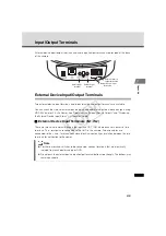
Input/Output Terminals
External Device Output Terminals (OUT1, OUT2)
There are two sets of external device output terminals (OUT1, OUT2), where each set consists of
two terminals. Each terminal set has no polarity. The condition between the two terminals can be
switched between connected and disconnected by controlling from the viewer. The output
terminals are isolated from the internal circuits of the camera using optical couplers.
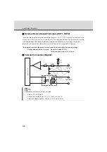
The loads connected to the output terminals should be used within the following ratings:
Ratings between output terminals: Maximum voltage 50 VDC
Continuous load current 100 mA max.
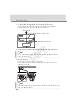
Internal Connection Diagram
Tip
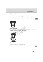
Applicable wire for external device cable
Single AWG No.28 to 22
Conductor size
Φ
0.32 to 0.65 (mm) (0.013 to 0.026 in)
Strip the cable by approx. 8 to 9 mm (0.315 to 0.354 in).
Inter
nal controller
External
de
v
ice
External
de
v
ice
Inp
u
t terminal
I
N
1, I
N
2
O
u
tp
u
t terminal
OUT1, OUT2
10k
Ω
10k
Ω
10k
Ω
+3.3
V
+
-
0.1
µF
COP
Y