background image

xv

Safety Precautions

Precautions for Use 


Warning 

• If smoke, abnormal noise, heat, odor or any other abnormality is detected, 

immediately stop using the camera and contact your nearest Canon dealer. 

Continuing to use the product may result in fire or electric shock. 

• Do not disassemble or modify the camera. 

• Do not put water or other liquid in the camera or splash or otherwise wet the 

camera.

• Do not put foreign objects in the camera. 

• Do not use sprays of flammable gases near the camera. 

• When the camera is not used for a long period, disconnect the LAN cable, 

external power supply and power connector for AC adapter (optional) from the 

camera. 

Fire or electric shock may result. 

Note

• Do not use this camera for medical devices and other systems that affect human 

life. 

Delayed or missing image transmission may occur depending on the PC and 

network environment, and thus high image transmission accuracy cannot be 

assured. 

Canon will assume no liability for any accident or damage resulting from use of 

the VB-C500VD/VB-C500D in the aforementioned devices or systems. 

• Do not capture the sun, halogen lamps and other very bright light sources or 

subjects. 

• Do not apply strong impact or vibration to the VB-C500VD/VB-C500D.

Malfunction may result. 

This installation should be made by a qualified service person and should 

conform to all local codes.

Summary of Contents for VB-C500VD

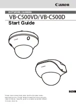
Page 1: ...tart Guide Please read carefully Start Guide and the Operation Guide Especially be sure to read Safety Precautions before using the network camera Keep this guide in a readily accessible location for...

Page 2: ...MAY BE ENTITLED TO AND TO THE FULL EXTENT PERMITTED BY LAWS AND REGULATIONS 1 NEITHER CANON INC NOR ANY OF ITS SUBSIDIARIES OR AFFILIATES MAKE ANY WARRANTY OF ANY KIND EXPRESS OR IMPLIED WITH REGARD T...

Page 3: ...of Items 2 and 3 above Notes on privacy and publicity rights regarding the utilization of video audio When using the VB C500VD VB C500D for video or audio recording it is the responsibility of the us...

Page 4: ...lfunction failure of RM Lite or other factors may cause problems such as recording failure recorded data corruption or loss Canon shall have no liability whatsoever for any loss or damages incurred by...

Page 5: ...ntribute to the effective usage of natural resources For more information about the recycling of this product please contact your local city office waste authority approved scheme or your household wa...

Page 6: ...icense conditions are also available in the License folder on the same Setup CD ROM Software under GPL and LGPL If you would like to obtain the source code under GPL LGPL please contact the dealer whe...

Page 7: ...C500 Viewer 1 10 Network Video Recording Software RM Lite 1 11 Notes on Operating Environment 1 12 Notes on Use When the Windows Firewall Function is Enabled 1 12 Notes on Use with Windows Server 200...

Page 8: ...era 2 10 Perform Initial Setting of the Camera 2 10 Check the Video Captured by the Camera 2 13 Step 4 Install the Camera 2 15 Installation Procedure for Direct Mounting on a Ceiling Wall 2 16 Install...

Page 9: ...Installer for VB Initial Setting Tool and VBAdmin Tools RMLiteInstall exe Installer for Network Video Recording Software RM Lite LICENSE Folder containing various license information BundledSoftware...

Page 10: ..._E pdf This document explains the basic setup procedure for the VB C500VD VB C500D how to use VBAdmin Tools and VB C500 Viewer troubleshooting etc Operation Guide can be found on the Setup CD ROM Refe...

Page 11: ...ing against the instruction accompanied by this symbol may result in death or injury Be sure to observe this precaution to use the product safely Caution Inappropriate handling against the instruction...

Page 12: ...apter can be connected to VB C500VD VB C500D from a standard AC power outlet Please check your instruction manual to make sure that your VB C500VD VB C500D is compatible with this adapter The socket o...

Page 13: ...ur in a particular installation If this equipment does cause harmful interference to radio or television reception which can be determined by turning the equipment off and on the user is encouraged to...

Page 14: ...e relevant regulations such as technical standards for electrical installations When installing the VB C500VD VB C500D select a ceiling surface etc capable of withstanding the total weight of the came...

Page 15: ...r supply and power connector for AC adapter optional from the camera Fire or electric shock may result Note Do not use this camera for medical devices and other systems that affect human life Delayed...

Page 16: ...r as they might not work as accurately as expected under certain conditions Canon will assume no liability for any accident or damage resulting from use of these functions Warning Do not use any AC ad...

Page 17: ...on Procedure for Direct Mounting on a Ceiling Wall P 2 16 in Chapter 2 Initial Setting and Installation of Camera 2 Dampen a soft cloth with water or diluted neutral detergent and wipe the soiled area...

Page 18: ...xviii Safety Precautions...

Page 19: ...Before Use The following explains the features of this camera bundled software operating environment and name and function of each part...

Page 20: ...ch as in condominiums and hotel stores It can be installed in various ways such as directly mounted on a ceiling or wall or recessed into a ceiling or wall Capturing Color Images at 0 2 Lux With its h...

Page 21: ...h image quality and high speed communication such as simultaneous distribution of JPEG and MPEG 4 Simultaneous Distribution of JPEG and MPEG 4 Video compression adopts JPEG MPEG 4 to achieve high imag...

Page 22: ...l Duplex A microphone or speaker with amplifier can be connected 1 to the camera to transmit receive audio full duplex via the viewer 2 You can select a desired audio input mode from LINE IN and MIC I...

Page 23: ...4 Users other than Administrators need not install this tool VBAdmin Tools Overview of VBAdmin Tools in Operation Guide VBAdmin Tools are for visually setting motion detection and for displaying logs...

Page 24: ...B C500VD VB C500D setting page VB C500 Viewer is already built into the camera and need not be installed beforehand P 2 4 Only JPEG can be displayed To display MPEG 4 video install RM Lite Viewer P 1...

Page 25: ...se RM Lite Viewer Recorded video saved in the storage server can be played or live video JPEG MPEG 4 can be displayed as it is captured by the camera Up to four cameras can be registered for the viewe...
Page 26: ...ge Server Recording formats JPEG only JPEG MPEG 4 H 264 Max recording frame rate 5 fps 30 fps 1 Recording schedule Weekly schedule recording Weekly schedule recording Special Day schedule recording Re...

Page 27: ...ommunication Audio can be transmitted received between the VB C500VD VB C500D and viewer Viewer type Live video display Audio VB C500 Viewer JPEG Receive audio from the VB C500VD VB C500D one way comm...

Page 28: ...ltimate Business Enterprise Home Premium SP2 32 64bit Windows 7 Ultimate Professional Enterprise Home Premium 32 64bit Windows 7 Ultimate Professional Enterprise Home Premium SP1 32 64bit Windows Serv...

Page 29: ...32 64bit Windows Server 2008 Standard SP2 32 64bit Windows Server 2008 R2 Standard SP1 64bit Memory 2 GB or more Hard disk 200 MB of disk space is required for installation additional 500 MB is requi...

Page 30: ...licked this warning dialog box will no longer appear If the Windows Security Alert dialog box is not displayed the warning function of the Windows firewall may be disabled Follow the procedure below t...

Page 31: ...03 and Windows Server 2008 the security level for Internet sites and intranet sites on Internet Explorer is set to High by default Accordingly when you access the top page of the camera VB C500 Viewer...

Page 32: ...og box in step 1 and see the displayed overview Note that even when the contents block dialog box does not appear setting pages and operations of VB C500 Viewer may still be limited because JavaScript...

Page 33: ...of registering the camera s top page as a trusted site Notes on Use with Windows Server 2008 Enabling the Sound Function to Use Audio In Windows Server 2008 the sound function is disabled by default...

Page 34: ...Running message appears Click Yes 4 The Sound dialog box appears Click the Playback tab to confirm that an audio device has been installed If no audio device is installed check the manual for your PC...

Page 35: ...s Video Storage Folder Do not specify the Windows folder or Program Files folder on the system drive as the folder for storing snapshots and specified video files Images and videos cannot be saved in...

Page 36: ...Inner Cover Camera Interior 1 Dome case 2 Inner cover 3 Varifocal lens Horizontal viewing angle 82 4 Focus lock screw 5 Zoom adjustment knob 6 Rotation lock screw 7 Pan lock screw 8 Tilt lock screw 9...

Page 37: ...P 2 25 2 Other steady state Unlit 12 VIDEO OUT terminal 13 Mounting screw hole Use this hole to affix the camera on an installation surface or affix an optional Recessed Mounting Kit 14 Zoom lock scr...

Page 38: ...18 Tripod mounting screw holes VB C500D only 19 MAC address Unique address of this camera Write down this address before install ing the camera P 2 10 20 LAN connector 100Base TX Cable length 300mm 1...

Page 39: ...e camera to an audio input output device speaker microphone etc The long end has cable marker from the bifurcation point in the cable corresponds to the audio output terminal The short end does not ha...

Page 40: ...a contact input output device sensor warning lamp etc For details see External Device I O Terminals P 3 6 Power Interface Cable WP500 VB Use this interface cable UL VW 1 Cable to connect the camera to...

Page 41: ...C Adapter PA V17 PA V18 Use this adapter when a PoE HUB or external power supply is not used RM Lite Additional Viewer License RM Lite Additional Viewer License is an additional license needed to inst...

Page 42: ...multiple sites Example of RM 64 RM 25 RM 9 Viewer screen Tip The VB C500VD VB C500D can also be used with Network Video Recorder VK series v2 0 or later However the RM series and VK series are not com...

Page 43: ...he camera First install the necessary software from the bundled Setup CD ROM Next connect the camera to the network and perform initial setting of the camera Check the video using VB C500 Viewer and t...

Page 44: ...ect the VB C500VD VB C500D and PC to the network P 2 6 If a PoE HUB or Midspan is used consult your Canon sales representative The figure shows an example of connection via a PoE HUB Step 1 Install th...

Page 45: ...ial Setting Tool and perform initial setting of the camera P 2 10 Check the image using VB C500 Viewer P 2 13 Install the VB C500VD VB C500D securely P 2 15 Step 3 Perform initial setting of the camer...

Page 46: ...mera settings P 2 10 Users other than Administrators need not install this tool VBAdmin Tools This software is used to manage the camera Chapter 2 in Operation Guide Users other than Administrators ne...

Page 47: ...g that all other applications have been closed click the Start menu and then select My Computer 2 Double click the displayed CD ROM icon APPLICATIONS Folder and then click VBToolsInstall exe 2 The ini...

Page 48: ...able from a PoE HUB conforming to IEEE 802 3af The figure shows an example using VB C500D If an AC adapter optional or external power supply is used connect it as shown below For details see Use of Ex...

Page 49: ...or Midspan see the operation manual or other documentation that comes with the applicable device For the LAN cable connecting the camera and a PoE HUB use a cable of Category 5 or higher of a length...

Page 50: ...he instructions provided in Precautions for Use of Optional AC Adapter PA V17 PA V18 P xvi in Safety Precautions The current may be limited for each port depending on the PoE HUB used However the came...

Page 51: ...VDC 10 Current supply capacity per camera 0 36 A If a 12 VDC battery power supply is used be sure to connect a resistor of 0 5 to 1 0 20 W or more to the power line Use double insulated devices for t...

Page 52: ...pe VB Initial Setting Tool Double click the icon on the desktop 2 VB Initial Setting Tool automatically detects the camera connected to the network and displays the MAC address IP address and model na...

Page 53: ...e cautionary information that should be heeded depending on your operating environment Before the initial setting see Notes on Operating Environment P 1 12 Tip The factory default Administrator passwo...

Page 54: ...Setting Tool which enables to communicate with the PC for setting Then change the IP Address Setting for LAN to Auto DHCP in Network in the Setting page See LAN Operation Guide The camera will stop i...

Page 55: ...dress of the camera whose operation you want to check and then click Settings 2 The web browser starts and the top page of the camera is displayed Click VB Viewer from VB C500 Viewer Note There may be...

Page 56: ...ting Page Admin Viewer Be sure to change the administrator password for security reasons See Administrator Password Operation Guide To display both JPEG and MPEG 4 video install and use RM Lite Viewer...

Page 57: ...hased the product Wire the VB C500VD VB C500D power supply network or other cables safely and securely according to the relevant regulations such as technical standards for electrical installations Wh...

Page 58: ...ll as wiring holes if necessary using the supplied template The figure shows the template for VB C500D VB C500VD VB C500D Roof space Ceiling board Fix to an anchor or structure Safety Wire LAN cable P...

Page 59: ...n the two dome case lock screws on the side face of the camera Loosen the screws until they are sticking out 3 To connect various interface cables audio I O power remove the cable cover at the bottom...

Page 60: ...cables and camera have dedicated connectors and connection terminals respectively You can select a desired direction from which to take out the interface cables and other wirings For the types of inte...

Page 61: ...fix the cable cover with a screw Wiring on a Ceiling Cut out the tabs and the side face on the cable cover Guide the interface cables out towards the side face of the camera as in the figure below and...

Page 62: ...able in the specified groove as shown below If the cable is not properly installed it may come off and cause the camera to malfunction Power Audio I O Interface cable fixing method Affixing groove for...

Page 63: ...nd affix the cable cover with a screw Note Affix each interface cable in the specified groove as shown below If the cable is not properly installed it may come off and cause the camera to malfunction...

Page 64: ...e as shown below At this time make sure the heat shrinkable tubes that protect the cables rest properly in front of the affixing grooves If the cable is not properly installed it may come off and caus...

Page 65: ...the audio I O or power interface cable to each external device 7 Affix the camera on the ceiling Remove the protection sticker from four camera mounting screw holes on the bottom of the camera Then al...

Page 66: ...viewing angle Adjust the zoom by moving the zoom adjustment knob and part A in the figure below at the same time Adjust the focus by moving the focus ring When all adjustments are complete tighten th...

Page 67: ...boot the camera from the setting page to end the installation mode Take note that the installation mode ends automatically after 30 minutes If you want to continue with the focus adjustment press the...

Page 68: ...2 26 Step 4 Install the Camera 11 Install the inner cover VB C500VD Remove the damper lock plate 12 Place the dome case on the camera and affix it by tightening the dome case lock screws...

Page 69: ...embled in ceiling bracket using four screws Make sure the interface cables are passed through in the direction of the opening in the in ceiling bracket as in the figure below Use the screws supplied w...

Page 70: ...pplied template to open screw holes for the Backside Ceiling Bracket and in ceiling bracket 3 Install the Backside Ceiling Brackets at the back of the ceiling wall and secure it with screws 4 Connect...

Page 71: ...eiling bracket on the screws that were loosely secured in step 3 turn the bracket clockwise and securely tighten affix the screws The figure shows VB C500D 6 Adjust the camera angle and focus in the s...

Page 72: ...ver Align the mark c on the recessed mounting cover with the mark I on the in ceiling bracket and turn the cover clockwise up until the mark I on the recessed mounting cover to affix the bracket in po...

Page 73: ...Appendix This section explains the external dimensions specifications external device input output terminals audio input output terminals etc...

Page 74: ...3 2 External Dimensions VB C500VD 155mm 6 10 in 118mm 4 65 in 112mm 4 41 in 76mm 2 99 in Bottom 95mm 3 74 in 4 4 6mm 0 16 0 18 in...

Page 75: ...4 25 in 110mm 4 33 in 64mm 2 52 in Bottom 136mm 5 35 in 95mm 3 74 in 4 4 6mm 0 16 0 18 in 8 M4 0mm 0 31 M0 16 in 112mm 4 41 in 120 64mm 2 52 in 110mm 4 33 in 215mm 8 46 in 63mm 2 48 in 98mm 3 86 in 1...

Page 76: ...on is possible Video size JPEG 640x480 320x240 160x120 Images of 3 sizes can be distributed simultaneously MPEG 4 640x480 320x240 Fixed to 1 size Video quality JPEG MPEG 4 5 levels With JPEG a desired...

Page 77: ...cable non polar Power consumption When PoE is used approx 3 3 W max Dedicated AC adapter PA V17 used approx max 4 5 W 100 V AC approx max 4 5 W 240 V AC Dedicated AC adapter PA V18 used approx max 4...

Page 78: ...I O Terminals Two external device input terminals and two external device output terminals are available VB C500 Viewer and RM Lite Viewer can be used to check the conditions of external device input...

Page 79: ...as no polarity The condition between the two terminals can be switched between connected and disconnected by controlling from the viewer The output terminals are isolated from the internal circuits of...

Page 80: ...he camera to an audio input output device use a dedicated audio interface cable WA500 VB P 1 21 Use a 3 5 monaural mini jack connector to connect the audio interface cable and audio input output devic...

Page 81: ...one can be connected Input terminal 3 5 mm mini jack monaural Dynamic MIC IN setting Input impedance 1 75 k 20 Supported microphone Output impedance 400 600 Capacitor MIC IN setting Input impedance mi...

Page 82: ...crophone used To send audio to speaker use RM Lite Viewer Audio cannot be sent from VB C500 Viewer P 1 9 Video and audio may sometimes lose synchronism Audio may be interrupted depending on the perfor...

Page 83: ...3 11 Input Output Terminals Appendix...

Page 84: ...CANON INC 30 2 Shimomaruko 3 chome Ohta ku Tokyo 146 8501 Japan CANON EUROPA N V Bovenkerkerweg 59 1185 XB Amstelveen The Netherlands YT1 1421 002 CANON INC 2013...

Reviews: