


5
5
5-5
5-5
Adjustment > Dip Switch Function > Motor Operation Check Mode > List of Motor Operation Check States
Adjustment > Dip Switch Function > Motor Operation Check Mode > List of Motor Operation Check States
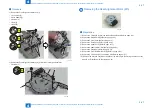
Motor Operation Check Mode
■
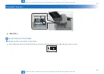
Entering the Motor Operation Check Mode
(1) With the host machine turned off, set the DIP switch (SW2) as shown below. While pressing down the push switch (SW2), turn on the host machine.
ON 1 2 3 4
■
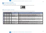
List of Motor Operation Check States
By setting the DIP switch (SW1) according to the following table after entering the motor operation check mode, you can check the operation of each motor.
No.
DIP Switch (SW1) Setting
Name
Operation
1
2
3
4
1
ON
OFF
OFF
OFF Feed Motor (M1)
Pressing down the push switch (SW2) each time drives the feed motor with the feed speed changed as follows:
Feed speed 102 -> 138 -> 204 -> 250 -> 300 -> 350 -> 400 -> 450 -> 500 mm/sec -> Stop
2
OFF
ON
OFF
OFF Delivery Motor (M2)
Pressing down the push switch (SW2) each time drives the delivery motor with the feed speed changed as follows:
Feed speed 102 -> 138 -> 204 -> 250 -> 300 -> 350 -> 400 -> 450 -> 500 -> 700 mm/sec -> Stop
3
ON
OFF
ON
OFF Paddle Motor (M3)
Pressing down the push switch (SW2) drives the paddle motor to rotate the paddle once.
4
ON
ON
OFF
OFF Front Alignment Motor (M4)
Pressing down the push switch (SW2) each time drives the front alignment motor to move the front alignment plate
as follows:
Minimum-width paper alignment position -> Maximum-width paper alignment position
5
OFF
OFF
ON
OFF Rear Alignment Motor (M5)
Pressing down the push switch (SW2) each time drives the rear alignment motor to move the rear alignment plate
as follows:
Minimum-width paper alignment position -> Maximum-width paper alignment position
6
OFF
ON
ON
OFF Tray Auxiliary Guide Motor (M6)
Pressing down the push switch (SW2) each time drives the tray auxiliary guide motor to move the tray auxiliary
guides as follows:
Support position -> Home position (retracted position)
7
ON
ON
ON
OFF Gripper Motor (M7)
Pressing down the push switch (SW2) drives the gripper motor to operate the gripper by one cycle.
8
OFF
OFF
OFF
ON
Stack Tray Shift Motor (M8)
Pressing down the push switch (SW2) each time drives the stack tray shift motor to move the stack tray as follows:
Stack tray lower limit position -> Stack position
9
ON
OFF
OFF
ON
Staple Motor (M9)
Pressing down the push switch (SW2) drives the staple motor to operate the stapler by one cycle.
F-5-4
T-5-2
Summary of Contents for Staple Finisher-S1
Page 6: ...Safety Precautions Notes Before Servicing Points to Note at Cleaning ...
Page 8: ...1 1 Product Outline Product Outline Features Specifications Names of Parts ...
Page 36: ...3 3 Periodic Servicing Periodic Servicing List of Work for Scheduled Servicing ...
Page 94: ...5 5 Adjustment Adjustment Adjustment Item Dip Switch Function ...
Page 113: ...Appendix Service Tools General Circuit Diagram ...


