


4
4
4-7
4-7
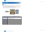
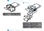
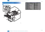
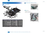
Parts Replacement and Cleaning Procedure > List of Parts > List of Connectors
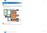
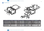
Parts Replacement and Cleaning Procedure > List of Parts > List of Connectors
[5]
[8]
[6]
[9]
[7]
[10]
[11]
[13]
[12]
[2]
[4]
[3]
[1]
Key No.
J No.
Symbol
Name
Relay connector
Key No.
J No.
Symbol
Name
Remarks
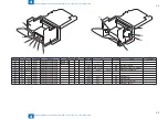
[1]
J8
P8
PCB1
Finisher Controller PCB
J8-1
P8-1
[5]
P8-11
-
S9
Stack Tray Paper Height Sensor
[1]
J8
P8
PCB1
Finisher Controller PCB
J8-2
P8-2
[6]
P8-12
-
S6
Tray Auxiliary Guide HP Sensor
[1]
J8
P8
PCB1
Finisher Controller PCB
[7]
P8-3
-
S4
Front Alignment Plate HP Sensor
[1]
J8
P8
PCB1
Finisher Controller PCB
[8]
P8-4
-
S3
Paddle HP Sensor
[2]
J13
P13
PCB1
Finisher Controller PCB
[9]
P13-1
-
S8
Gripper Encoder Sensor
[3]
J11
P11
PCB1
Finisher Controller PCB
P6-2
P6-2
[10]
P11-11
-
S14
Staple Paper Detection Sensor
[4]
J6
P6
PCB1
Finisher Controller PCB
[11]
P6-1
-
M6
Tray Auxiliary Guide Motor
[4]
J6
P6
PCB1
Finisher Controller PCB
P6-2
P6-2
[12]
P6-12
-
M4
Front Alignment Motor
[4]
J6
P6
PCB1
Finisher Controller PCB
[13]
P6-3
J6-3
M7
Gripper Motor
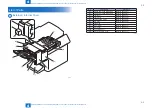
F-4-9
T-4-9
Summary of Contents for Staple Finisher-S1
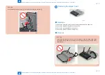
Page 6: ...Safety Precautions Notes Before Servicing Points to Note at Cleaning ...
Page 8: ...1 1 Product Outline Product Outline Features Specifications Names of Parts ...
Page 36: ...3 3 Periodic Servicing Periodic Servicing List of Work for Scheduled Servicing ...
Page 94: ...5 5 Adjustment Adjustment Adjustment Item Dip Switch Function ...
Page 113: ...Appendix Service Tools General Circuit Diagram ...


