COPYRIGHT © 2001 CANON INC.
2000 2000 2000 2000
CANON SmartBase PC1200s/iR1200s REV. 0 DEC. 2001
5-17
CHAPTER 5 MECHANICAL SYSTEM
2.2 PCBs
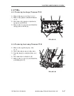
2.2.1 Removing the Image Processor PCB
1) Remove the rear cover. (See 2.1.1.1)
2) Remove the printer controller PCB.(See
2.2.5)
3) Disconnect all connectors from the im-
age processor PCB [1].
4) Remove the 6 screws [2], and detach the
image processor PCB [1].
[2]
[2]
[2]
[2]
[1]
[2]
F05-202-01
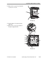
2.2.2 Removing the Analog Processor PCB
1) Remove the copyboard glass. (See
2.1.3)
2) Move the contact sensor to the center.
3) Free the hook [1], and detach the cover
[2].
4) Disconnect the 2 connectors [3].
5) Remove the 2 screws [4], and detach the
grounding plate [5].
[2]
[3]
[5]
[1]
[4]
F05-202-02


