background image


- 3 - 

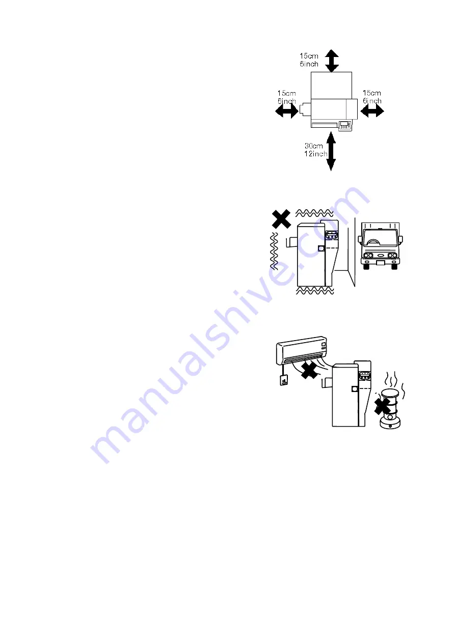
  Enough space must be provided around the 

    equipments.    This is necessary for easy   


  operation as well as for ventilation. 


  If the ventilation opening is closed by   


  obstacle, heat cannot be dissipated and   


  it may cause a fire.   

    ( Place with the clearance as shown in 


  the illustration. ) 


  Do not place in the room with much   

    vibration.    It may cause troubles on the 
    equipments. 


  Do not place in such place where the 

    temperature changes rapidly.    If the   
    cold room is suddenly heated it may   
    cause condensation on the equipments   
    and damage the print quality or even   
    printing function itself.     


Summary of Contents for PR-C151

Page 1: ...DIRECT CARD PRINTER Operation Guide ...

Page 2: ......

Page 3: ...es 11 Ink Ribbons Card c Parts to be replaced periodically 12 Print Head Input Roller Fan Filter d Cleaning Card 13 Cleaning Card e Name of the parts 14 Section 3 Installation a Environment for installation 18 b Space for installation 18 c Preparation for installation 18 d Connecting the Printer to Computer 19 Setting Printer ID Internet Connection Settings Connecting Cable e Power ON 22 f Setting...

Page 4: ...adjustments Image Set Up ON OFF of the error buzzer Error Buzzer Ribbon setting type Printer Ribbon Display Printer ID No Printer ID Disp Setting the System Environment Printer Status Interface Settings Interface Setup Device Version Information ROM Version Printer Settings Initialization Setup Data Reset e Structure of User Mode 30 Section 5 How to Set Cards and Ribbon a Setting cards 32 b Settin...

Page 5: ...the equipment Section 10 Trouble and Countermeasure a Troubles displayed on the operation panel 49 Display of trouble on the LCD panel Basic operation to release troubles Trouble shooting b Releasing card jam 53 Block Layout Card Jam which cannot be released by Clear key c Troubles which are not displayed on the operation panel 56 Troubles relating to print image Other troubles ...

Page 6: ...danger of death or serious injury This indicates that there is possibility of death or serious injury This indicates that there is a possible cause of injury and or damages on properties This manual MUST be read fully before operating the printer a Before installing 2 Page b Before turning the power on 4 Page c Before using 5 Page d Before moving the equipment 8 Page e Other 9 Page f Prohibited ma...

Page 7: ...tall the equipments near the heat emitting apparatus such as stove and heater or near the flammables such as curtain It may cause fire Do not place on shaky table or inclined location It may fall or drop and cause injury to nearby persons Do not place where there is direct sunlight It may cause deformation of plastic housing and discoloration of the prints ...

Page 8: ...e dissipated and it may cause a fire Place with the clearance as shown in the illustration Do not place in the room with much vibration It may cause troubles on the equipments Do not place in such place where the temperature changes rapidly If the cold room is suddenly heated it may cause condensation on the equipments and damage the print quality or even printing function itself ...

Page 9: ...If used without removing a small amount of electricity runs continuously through the dust by the effect of moisture etc and may eventually cause a fire Be careful so that the power supply cord is not damaged If the cord is twisted pulled strongly or placed underneath a heavy object it may be damaged and become a cause of fire Do not handle the plug with wet hand because it may cause electric shock...

Page 10: ...re or electric shock If by any chance metal pieces or water get inside the equipment turn off the main switch and plug off the power supply cord from the outlet Then contact the dealer from whom you have purchased the equipment Using as it is may cause fire or electric shock Do not open the panel or cover which is fixed with screws other than directed by the manual There is live part carrying high...

Page 11: ...er from whom the equipment was purchased In case of thunder for the purpose of safety turn OFF the main switch and plug off the power cord This will prevent burning of the equipment fire or electric shock If the equipment will not be used for a long period turn OFF the main switch and plug off the power cord for safety Deterioration of insulation may cause electric shock or leakage and fire ...

Page 12: ... may cause card jamming or malfunction of the equipment Do not touch any part inside the equipment other than directed by this manual Read this manual carefully before performing recovering operations for card jamming or other malfunctions Do not attempt to operate in any other way than designated in this manual Such attempt may cause unexpected damage on the equipment If electric leakage occurs f...

Page 13: ...supply cord from the outlet before moving the equipment Otherwise it may damage the power cord and cause a fire To pull off the plug of the power cord hold the body of the plug and pull off If the cord is held and pulled the core lines may be pulled out or broken and cause fire or electric shock Caution ...

Page 14: ... connected to separate power line and place the equipment as far as possible from them 1 f Prohibited matters The law prohibits to use the portrait photographs paintings of a person or use the copyright products illustrations logos etc without permission Do not use this equipment for the unauthorized use of the copyrighted products or for other unlawful purpose ...

Page 15: ...ontents Following items are packed in the carton together with the printer If anything is missing contact the dealer from whom you have purchased Power SupplyCord EmptyBobbin Cleaning Card Stacker Box Weight Ferrite core Operation Manual CD ...

Page 16: ...sible with one roll of ink ribbon Ink ribbon has been changed in the middle There has been errors in the middle Head lifting has been done in the middle Abnormal operation which is not allowed in this manual was done Ink ribbon must be stored in the cold and dark place and kept away from organic solvent or diazo copying machine Use as early as possible Maximum storage period is 6 months after deli...

Page 17: ...s with fingers Static may damage the circuits inside this part At the printing edge of the Print Head is very high compound of heating element So never touch this part with a hard object fingers or stained materials Standard replacement cycle for the Head is 20 000 frames of printing with the following standard printing condition Full color image portion 25 4mm in length 1inch Black characters 38 ...

Page 18: ... Replacing Input Roller at 7 a For cleaning the Rollers refer the item Input roller at 6 a Fan Filter Recommended Replacement period every 6 months Do not wash with water It may cause equipment trouble See page 46 for replacement 2 d Cleaning Card Cleaning Card Use to make cleaning of card transportation rollers See page 41 for the way to clean The cleaning card is designed as one time use Caution...

Page 19: ... 14 2 e Name of the parts Front side of the printer Front Access Cover Top Cover Rear Cover Operation Panel Card Feeding Unit Power Switch Reject Card Exit Front Cover Right Cover Fan Filter ...

Page 20: ... 15 Rear side of the printer Power Cord Receptacle USB Connector Optional Unit Connector Ethernet Connector Left Cover Exit Box Mount Eject Card Exit ...

Page 21: ... 16 Front Access Panel Input Roller Module Ribbon Cartridge Holding Lever Manual Rotation Knob Ribbon Cartridge ...

Page 22: ... 17 MEMO ...

Page 23: ...ic field It may destruct the magnetic encoding data if the Magnetic Encoder is being used In the worst case it may cause equipment trouble 3 b Space for installation The space for the operation as shown in the illustration should be provided At least 20 cm 8inch of clearance should be kept for the Top Cover Table to place the printer should be able to hold Minimum 25Kg 55lbs and have flat top and ...

Page 24: ... Computer USB or LAN interface and RS 232C interface for IC R W No Description Interface Cable To Control a Printer USB 2 0 Not bundled To Control a Printer Ethernet 100BASE TX Operation guaranteed Not bundled USB Ethernet USB Ethernet ...

Page 25: ... be the same as that for the other device The system will not operate normally Internet Connection Settings Configure Internet connection settings to connect the printer to a network Configure these settings on the printer in User Mode or through the printer driver 4 d Function of User Mode Connecting Cable USB Cable Shape of the connector on a printer side B Type Connect the B type side to the ba...

Page 26: ...ector NonLPS LimitedPower Source for the options Refer to the printer back view in the Section 2 Name of the parts Connected device may be damaged Circuit voltage rating 24 Vdc 5 Vdc Fire risk when none designated device is connected When connecting the cable do not forget to turn OFF the power switch of the printer and all other devices to be connected It may cause a trouble to entire system and ...

Page 27: ...ltage drop as much as possible When the power is turned OFF wait for at least 3 sec before turning ON again Check that the power switch is OFF before connecting the power cord to the outlet 3 f Settings after the Power ON Set the Card and Ink Ribbon 5 a Setting the Cards 5 b Setting the ink ribbon Set the Operation Panel following the system instructions 4 d Setting the system environment in the p...

Page 28: ...swhilecommunicating ErrorLED Red IndicatesError Thisalarmsthattheprinterisinerror PowerLED Blue PowerONindicator ThisshowsthepowerisON RibbonChange MenuKey Normal Usethiskeywhentakingouttheribboncassettebefore theribbonisfinished Bypressingfor3secorlonger itmovestoUserMenu User UsethiskeyforthemenuselectionattheUserMode ClearKey Normal Useforclearingorresumingafterreleasingerror Bypressingfor3sec ...

Page 29: ...so that the printer is reset and returned to the status of after the power ON Change the Ink Ribbon To pull out the Ribbon Cassette containing the ribbon in the middle of operation for example to change the ribbon type or to check the amount of the Remaining ribbon press Menu Ribbon Change key The message on the LCD panel changes from Ready to Print to Ready to Print Removable Ribbon and the Ribbo...

Page 30: ...to move to the User Menu Then the first menu Card Count is displayed Basic Operation in the User Mode As the User Menu has the following layer structure select the desired item with the MENU key and change the setting values using EXE key or Clear key By pressing EXE key at EXE sub Menu it goes one layer below There are Return to Normal Menu or Return to Parent Menu selections at each layers By pr...

Page 31: ...nction Color Adjustment Configure print conditions for each inkcolor including Yellow Magenta Cyan and Black Yellow Adjust the hues of color for colorimages 1 Increasing values produces richer colors Decreasing values produce lighter colors Magenta Cyan Black Adjust thethickness of blackcharacters Increase values ifthin lines blur Decrease valuesif thicker linessmear Color Print Mode Configure the...

Page 32: ...uzzer Select ON OFF of the error alarm buzzer which sounds when the errors such as Cover Open or Card Empty occur Ribbon setting type Printer Ribbon YMCK01 for color printing and K01 for black letters are used as the standard ribbons for this printer Setting of the operation panel is required corresponding to the label of the ink ribbon type being used Some system does not display this item for th...

Page 33: ... Only Hi Co magneticencoder Encode First WhenthisisON magneticencodingisdonebeforeprinting EncodeMode Settheentrydirectionintothemagneticencoder frontorback IC R W Connect Configure IC R W connection status Multi Card Print Laminating magneticencodingandprintingareexecutedsimultaneously Depending on the system these functions may be invalid If the magneticencoder is not connected messages relating...

Page 34: ...CLEAR key and EXE key simultaneously to change to the change settings menu Device Version Information ROM Version This printer is equipped with the function to download the main program from the PC in order to support various card printing systems The program has two parts one is the Base Program which controls the basic communications and the other is the Main Program to control all functions In ...

Page 35: ...nu Printer Cleaning EXE sub menu Image Setup PushMENUKey Color Adjustment EXE submenu Color Print Mode Sharpness Adjust Printer Ribbon H Roller Ribbon Return to normal Mode EXE Return to Parent Menu EXE Color Adjustment PushMENUKey Yellow Magenta Cyan Black Return to normal Mode EXE Return to Parent Menu EXE High Speed ON Printer ID Disp ID RibbonType PushMENUKey Printer Status CLR EXE sub menu In...

Page 36: ...ENUKey Parallel Print on Card Eject Face Print Face Up Option Setup EXE submenu Return to normal Mode EXE Return to Parent Menu EXE F WVersion PushMENUKey Base Program Main Program Head Number Encoder Unit H Roller Unit Serial Number Return to normal Mode EXE Return to Parent Menu EXE F WVersion EXE sub menu Option Setup PushMENUKey EncoderType Encode First EncodeMode Multi Card Print Return to no...

Page 37: ... even 4 Place the card weight on top of the card and close the cover Hold the card s by the edge When loading the cards with mag stripe be careful to the direction of the card Regarding the direction read and follow the instruction manual If the direction is incorrect it becomes Encoder Write Error If mag stripes are on both sides it may be erroneously encoded When printing on the pre printed card...

Page 38: ...en loading the cards stack the cards evenly as marked with in the figure below If it is stacked unevenly as shown with the mark in the figure below it may cause Pick Up Error or the stack may collapse Caution ...

Page 39: ... and take out the Ribbon Cartridge without lifting the Print Head by pressing RIBBON CHANGE key Normal print quality of the next printing will not be obtained Do not leave the ink ribbon cartridge off hand When loading again take up the frame which has been exposed before inserting Dust on the ribbon or cartridge may cause a trouble on the print head Press Ribbon Change key about 1 sec Then make s...

Page 40: ...ake up side of the cartridge touse as take up bobbin Set new ribbon onto the supply side of the cartridge Peel off the leading tape at the beginning of new ribbon and put it onto the empty bobbin Attach the center of ribbon to the center of the bobbin as shown below Close and lock the cartridge turn the take up bobbin shaft some 2 3 turns in direction as shown by arrow in the figure and set the ca...

Page 41: ...in before restarting Correct printing may not be obtained if printed before the alcohol is completely dried Do not touch the rollers with hand Fingerprint may affect the quality of the printed image Although the interval of cleaning varies depending on the condition of the card the following period is recommended assuming that the cards are properly stored and handled Parts to be cleaned Number of...

Page 42: ...n Page 43 and clean in the following procedure Wet and squeeze a piece of soft cloth with alcohol for cleaning OA equipment and wipe in the direction as illustrated Rotate the roller slowly and clean all surface After cleaning wipe with a dry cloth and leave about 1 minute to dry up before reinstalling After wiping off wait till it becomes completely dry before inserting it again ...

Page 43: ...the top cover rotate the whole Flip Turn Module to the angle of easy to clean as using green handle as shown in the figure Prepare the cotton swab and put a few alcohol on it Touch the cotton swab to the surface of rubber rollers then rotate the these rollers as using green disk as shown in figure This cleaning is given for the all white mold rollers paired with rubber rollers as well ...

Page 44: ...the whole surface of all 4 pairs of rubber rollers and white mold rollers To clean them easily use t he green handle located on front access area as shown in figure on right This handle is used for rotating those rollers manually 6 d Cleaning of the Ribbon transport roller Before beginning this operation please read the general advice which appears in the beginning part of this section Press Ribbo...

Page 45: ... this operation please read the general advice which appears in the beginning part of this section Wet and squeeze the soft cloth with alcohol for OA equipments and wipe the all surface of the roller in the direction as shown by arrow in the figure below ...

Page 46: ...ing operation Otherwise an electrical shock or personal injury could result Do not use solvents other than alcohol for cleaning OA equipments Using the solvent other than alcohol may damage the parts and may cause trouble of the printer The heating elements are shown with in the figure on right W et and squeeze the soft cloth with alcohol for OA equipments and wipe the heating elements in the dire...

Page 47: ...e PUSH MENU KEY 3 MENU key Indication changes by pressing the MENU key Press it till the indication changes as shown on right Printer Cleaning 4 EXE key Remove a blank card for print from the card hopper Remove Normal Card 5 EXE key Put the cleaning card on card hopper with printed side up Note 1 It may cause trouble when the card set with printed side down Note 2 Push the card into a printer till...

Page 48: ...ames N A Print Head Every 20000 frames Philips ScrewDriver Loader Application Fan Filter Every 6 months Philips ScrewDriver Number of the printed frames is displayed on the LCD panel 7 a Replacing Input Roller Hold the tab and pull slightly till its frame can be hold Hold frame and pull the whole unit out Before setting the new unit the rollers on the new unit must be clean To put the new unit in ...

Page 49: ... next page showing a print head fixed showing a print head removed Take the part off See the figure at the top of next page To take the print head off Release the lever as pointed with C in fig Then hold the tab H of the head module and pull it out Take the connector off and fixed it onto the new head module To put the head module into the printer Release the lever C and slide in the head module a...

Page 50: ... 45 A B C D F G H A J 誤操作防止カバーを取り外します Takethe wrongoperation prevention cover off ...

Page 51: ...just below the card hopper Take off Fan Filter installed at the fan intake duct behind the right cover Put Fan Filter into inside the rib shown as in the figure on the right to fix Fan Filter Please be careful that in case Fan Filter is not firmly fixed foreign substance might be absorbed from the gap which can damage print head or printer Right cover installation screw Filter section X 2 Change t...

Page 52: ...rinting Size Max 85 5mm cardlongitudinal direction x 54 5mm cardtransverse direction 6 Printing Speed 28 seconds oneside excluding communication time at whole area printing at the size asshown above 7 Ink Ribbon Standard 3BP 5 panels 250images BK OP 2 panels 250images 8 Flip Turn Feature Standard 9 Supply method andcapacity 100 cards at card thickness 0 76mm supplied automatically 10 Interface USB...

Page 53: ...nit Printing Unit The card moves through this unit five times to be printed 3 colors black color and protective overlay coating Print Head is positioned Rectangular to the card transport line and pressed against the printing face of the card linked withthemovementofthecard TheimageisprintedbycontrollingtheheatofeachcellofthePrintHead Encoder Option Space This is the space for attaching the Encoder...

Page 54: ...ity Cover Open in this case is displayed on the LCD panel Close the cover and press Clear key Then the display changes to Card Empty Load the cards and press Clear key to return to Ready to Print When the message Cannot Recover PleaseReset isdisplayed remove thetroubleandpressandholdtheClearkeyformorethan3second ReleasetheClearkeyaftercheckingthedisplayhasbeen changed to Reset The printer is reset...

Page 55: ...eck thesettingoftypeontheencoder Check ifthetypeof thecardbeingusediscorrect P 32 Temperatureoftheprint heador insideof the equipment isoutofrange Temper aturearoundequipment isoutof range Make sureofambienttemperature is inthe rangeofwhat is mentioned inSection3 P 18 This messageisshownwhen theClearkeyis pressed without takingouttheribboncartridgewhen theinkribbonrelatederrors Pullout thecartridg...

Page 56: ...inkribbonisnotusedup To theend Theprinterbecomestoerrorandnormalprinting isnotpossible Checktheink ribbon P 34 P 34 Theribbon typesettingoftheprinterand theribbon typeactuallybeingused donotcorrespond Theribbonsticks to thecardandcard jamerror willoccur Pullouttheribboncartridgeandpeeloffthe ribbonfromthecard andturnthe takeupbobbinshaftsome 2 3 turns If theribbon isbroken useScotch tapeetc topatc...

Page 57: ...andcard jamerror willoccur Peeloff theribbon fromthecardand rollup theribbon2 3turns If theribbonisbroken useScotch tapeetc topatchupandrollup It mayrequirerepairingdependingof thecondition Theengagementteethof thebobbin isbrokenbydroppingetc Replacewith thenormalbobbin If thetakeupbobbin isdamaged unwind theusedribbonorcutoff the wounduppartof theribbon attachtheendtothenormalbobbinand winduptoth...

Page 58: ...icallytotheCardEjectExitbypressingClearkeyontheoperationpanel Ifthecard cannot be ejected in this method remove the jammed card manually The location Block of card jam is shown on the LCD panel The figures next to the Card Jam Area indicates the card jam location more closely Area Location 01 02 InsidetheFeederBlock 02 04 03 08 BetweenFeederBlockandFlipTurnBlock WithinFlipTurnBlockandeject Between...

Page 59: ... 54 Block Layout ...

Page 60: ...dealer P 40 AcardisstuckintheFlipTurnBlock First turnOFFthepower Openthetopcoverandremovethecard Ifnecessary rotatethe greenhandleand orgreendisktotransportintheflipturnunit tomovethecardtotheeasypositiontotakeout PressClearkey afterthecardisremoved Ifthiserrorrepeats cleantherollersintheFlipTurnBlock P 38 AcardisstuckinthePrintBlock PressRibbonChangekeyandtakeouttheribboncassettebefore turningOFF...

Page 61: ... to a part of the card causing abnormal printing Do not touch the printing surface of the card P 32 A thin unprinted line along the card transport direction appears A dust adheres on the print head Clean the print head If the problem is not solved by head cleaning a part of the heat element of the head is damaged Replace with the new head The damage of the print head is caused by biting a solid pa...

Page 62: ... P 41 P 44 P 44 Thecoloroftheprinted image suddenly changes in themiddle Iftheribbon cartridgeis takenout without pressing Ribbon Change keyand re setagain thefirstframe is printed and outputwith this trouble Whentakingout theribboncartridge with remaining ribbon do notforgettopress RibbonChange key beforetaking out The message RibbonTypeincorrect isshown on the LCD display Thisdoesnotmean the mac...

Page 63: ...ansmitted to theprinter CheckthatthePrinterID numberis notconflicting with otherdevice s Turn OFFthepowerofthesystemand turnON again Pleasebesure that theprinterand theother devices startbeforethecomputer Checktheconnectionofthecables P 20 P 19 Cutoftheribbon Printroller isdirty Cleanthe roller Refer to 6 c Cleaning of the Print Rollers P 39 ...

Page 64: ...4Y5 8690 040 CANON FINETECH NISCA INC 2018 ...

Reviews: