3-44
CHAPTER 3. REPAIR INSTRUCTION
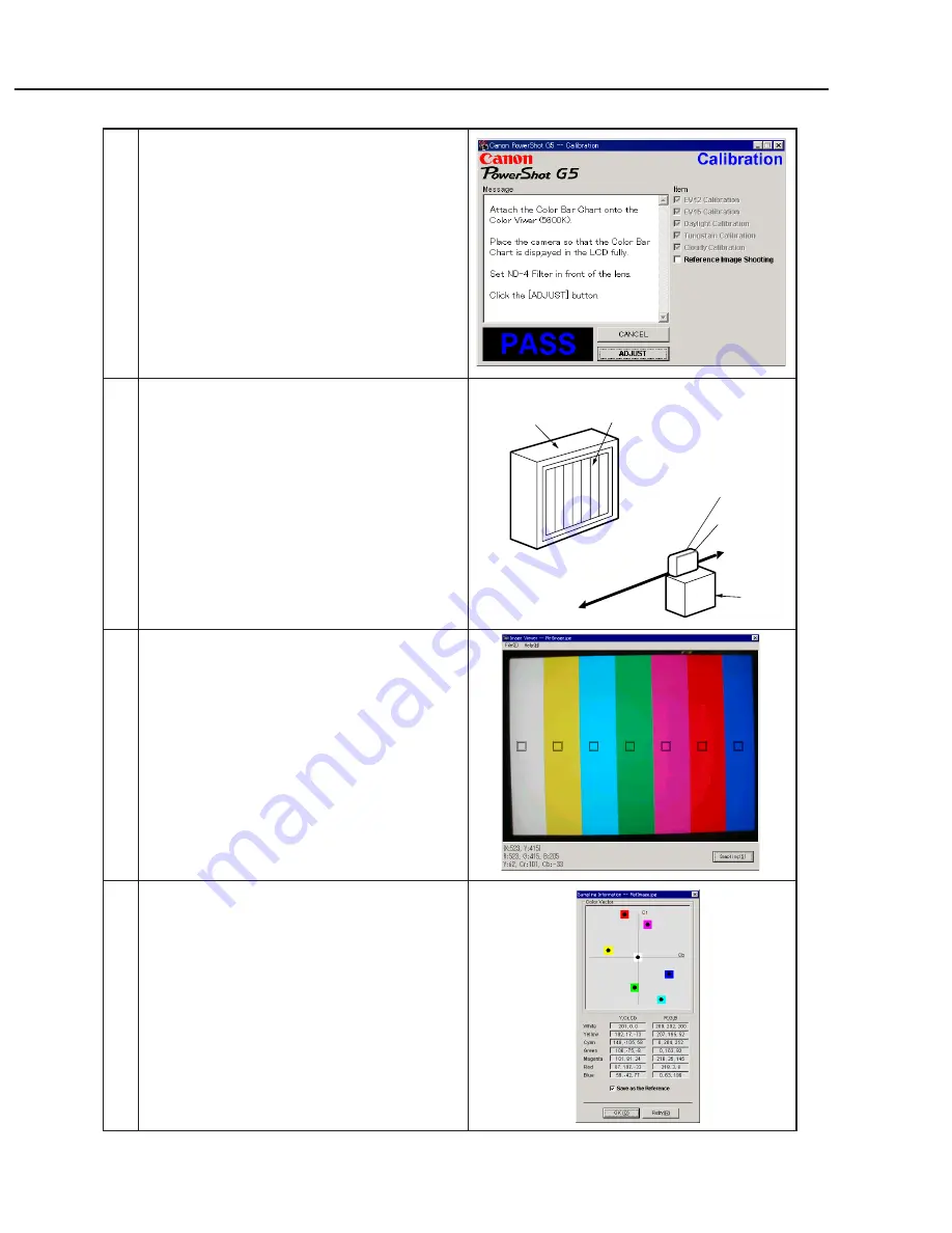
Color Viewer
Color Bar Chart
Personal
Computer
CAMERA
BODY
Power
Source
Stand
ND-4
Filter
12
When the message on the right appears go to 13.
13
1. Attach the Color Bar Chart to the Color Viewer.
2. Place the camera so that the Viewing image of
the color bar chart is the full of LCD with the
ND-4 Filter attached.
3. Click the “ADJUST” button.
14
1. Shift a frame on the display screen with a mouse
to choose a color of color bar.
2. Click the “Sampling” button.
15
Check “Save as the Reference”, and click the
“OK” button to store the data.
Summary of Contents for PowrShot G5
Page 1: ......
Page 10: ...1 6 ...
Page 11: ...1 7 ...
Page 12: ...1 8 ...
Page 19: ...3 3 Nomenclature Indicator LCD monitor 1 15 ...
Page 21: ...1 17 Intervalometer Save Settings ...
Page 30: ...1 26 4 2 Function s Availability and Data memory in Each Shooting Mode ...
Page 31: ...1 27 ...
Page 32: ...1 28 ...
Page 34: ...1 30 ...
Page 35: ...1 31 ...
Page 36: ...1 32 ...
Page 112: ...PowerShot G5 Pg2 INTERNAL PARTS SECTION 1 8 8 7 1 2 3 4 9 7 10 8 11 5 6 N S See Pg3 See Pg5 ...
Page 118: ...PowerShot G5 Pg5 EVF UNIT SECTION 1 10 2 5 3 7 12 11 12 4 6 8 13 9 a b a d c b d c ...
Page 120: ...PowerShot G5 Pg6 BATTERY BOX UNIT SECTION 8 4 8 2 3 7 1 5 8 8 8 6 ...
Page 122: ...PowerShot G5 Pg7 Fuse 2 1 DC DC CONVERTER PCB ASS Y ...
Page 148: ...C CANON INC 2003 01 JUNE 2003 3 4 HV MODULE UNIT ...
Page 149: ...C CANON INC 2003 01 JUNE 2003 3 5 TOP MODULE UNIT ...
Page 150: ...C CANON INC 2003 01 JUNE 2003 3 6 LCD PCB ASS Y ...
Page 151: ...C CANON INC 2003 01 JUNE 2003 3 7 OPTICAL FLX ...
Page 152: ...C CANON INC 2003 01 JUNE 2003 3 8 EF FLX ...
Page 153: ...C CANON INC 2003 01 JUNE 2003 3 9 R_EN FLX ...
Page 154: ...C CANON INC 2003 01 JUNE 2003 3 10 CCD FLX ...
Page 156: ...PowerShot G5 Auto Focus Chart 1 ...
Page 157: ...PowerShot G5 Auto Focus Chart 1 ...
Page 158: ...AF Chart Dimensions 1 Dimensions 1 88mm 65mm ...
Page 159: ...PowerShot G5 Auto Focus Chart 2 ...
Page 160: ...PowerShot G5 Auto Focus Chart 2 ...


