3-30
CHAPTER 3. REPAIR INSTRUCTION
5
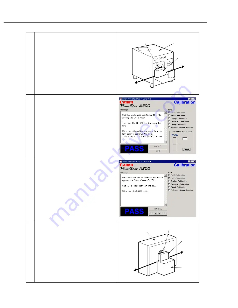
1. When the message on the right appears, Set the
Brightness Box to EV15 and attach the ND-8
Filter while setting the C-12 Filter between the
lens.
2. Click the “Check” button.
3. Check the Brightness level if it is within
0
±
5.
* If not, calibrate the Brightness Box until it
becomes within 0
±
5.
4. Click the “NEXT” button.
6
When the message on the right appears go to 7.
7
1. Attach the ND-2 Filters between the Lens and
the Color Viewer.
2. Place the camera so that the lens is set against
the center part of the Color Viewer.
3. Click the “ADJUST” button.
Personal
Computer
Power
Source
Brightness
Box
CAMERA
BODY
C-12 Filter
Power
Source
Stand
Color Viewer
Personal
Computer
CAMERA
BODY
ND-2
Filter
4
1. Place the camera so that lens is set against the
light source surface of the Brightness Box via
the C-12 Filter.
2. Set the Brightness Box to EV12.
3. Click the “Check” button.
4. Check the Brightness level if it is within
0
±
5.
* If not, calibrate the Brightness Box until it
becomes within 0
±
5.
5. Click the “NEXT” button.
Summary of Contents for PowerShot A300
Page 1: ......
Page 23: ...1 18 3 2 6 dimentional diagram 58 0 2 28 36 6 1 44 110 0 4 37 Unit mm inch ...
Page 24: ...1 19 3 3 Nomenclature ...
Page 27: ...1 22 Play MENU Protect Transfer Order Rotate Sound Memo Erase all Auto Play Print Order ...
Page 36: ...1 31 ...
Page 37: ...1 32 ...
Page 38: ...1 33 ...
Page 39: ...1 34 ...
Page 40: ...1 35 ...
Page 41: ...1 36 5 2 System Diagram ...
Page 99: ...PowerShot A300 Casing Parts Pg1 1 2 3 4 5 6 7 8 9 12 10 11 13 14 15 15 14 14 N S ...
Page 103: ...PowerShot A300 Pg3 Internal Parts 2 GRAY ORANGE 1 2 3 4 5 6 7 8 9 10 11 12 13 14 14 14 14 ...
Page 124: ...C CANON INC 2003 01 April 2003 3 3 OPR PCB ASS Y ...
Page 125: ...C CANON INC 2003 01 April 2003 3 4 RLS PCB ASS Y ...
Page 126: ...C CANON INC 2003 01 April 2003 3 5 BL FPC ASS Y ...
Page 128: ...PowerShot A300 Auto Focus Chart ...
Page 129: ...PowerShot A300 Auto Focus Chart ...


