


2-4
COPYRIGHT © CANON ELECTRONICS INC. 2012
CANON P-208 FIRST EDITION
CHAPTER 2 FUNCTION & OPERATION
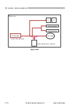
4. Electrical Circuits
An overview of the electrical circuits
block diagram of this machine is shown
below.
Control PCB
Feed motor
(With encoder)
CIS unit
(upper)
CIS unit
(lower)
Start switch
USB cable
Upper unit
sensor
Regist sensor
Document sensor
Tray switch
AutoStart switch
Figure 2-104


