Canon MP560 - PIXMA Color Inkjet Service Manual Download Page 50

4-2.  Service Mode  

(1)  Service mode operation procedures 

Use the Service Tool on the connected computer. 

1)  Start the machine in the service mode. 

i.  With the machine power turned off, while pressing the Stop button, press and hold the ON button. (DO 

NOT release the buttons.) 

ii.  When the Power LED lights in green, while holding the ON button, release the Stop button. 

(DO NOT release the ON button.) 

iii.  While holding the ON button, press the Stop button 2 times, and then release both the ON and 

Stop buttons. (Each time the Stop button is pressed, the Alarm and Power LEDs light 
alternately, Alarm in orange and Power in green, starting with Alarm LED.) 

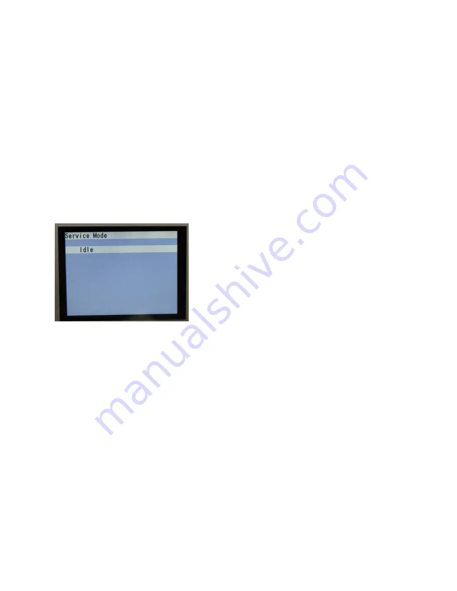
iv.  When the Power LED lights in green and the machine displays "Service Mode Idle," the 

machine is ready for the service mode operation. 


LCD ready for the service mode operation: 


2)  Start the Service Tool on the connected computer. 

i.  When a button is clicked in the Service Tool dialog box, that function is performed. During operation 

of the selected function, all the Service Tool buttons are dimmed and inactive. 

ii.  When the operation is completed, "A function was finished." is displayed, and another function 

can be selected. 

iii.  If a non-supported function is selected, "Error!" is displayed. Click 

OK

 in the error message 

dialog box to exit the error. 


47 / 64

Summary of Contents for MP560 - PIXMA Color Inkjet

Page 1: ...ght 2009 Canon U S A This technical publication is the proprietary and confidential information of Canon U S A which shall be retained for reference purposes by Authorized Service Facilities of Canon U S A Its unauthorized use is prohibited ...

Page 2: ...cement Parts 3 2 Part Replacement Procedures 1 External housing removal 2 Cable wiring and connection 3 Emblem removal 4 Carriage unlocking 5 ASF unit removal 6 Right chassis removal 7 Carriage unit removal 8 Spur unit and platen unit removal 9 Purge drive system unit right plate and switch system unit left plate removal 10 Engine unit reassembly 11 Ink absorber replacement 4 ADJUSTMENT SETTINGS 4...

Page 3: ...eed motor adjustment 3 Carriage unit replacement 4 Document pressure sheet sponge sheet replacement 5 Ink absorber counter setting 4 5 Verification After Repair 1 Standard inspection flow 2 Service test print 3 Ink absorber counter value print 5 MACHINE TRANSPORTATION TABLE OF CONTENTS ...

Page 4: ... ink absorber counter Service Tool 1 Perform in the service mode 1 min Ink absorber replacement When the ink absorber becomes full To replace the ink absorber with a new one Screwdriver a pair of tweezers etc 15 min Paper feed motor position adjustment At paper feed motor replacement To adjust the belt tension Position the paper feed motor so that the belt is stretched tight None 5 min N Automatic...

Page 5: ...lacement To maintain scanning accuracy hold the sheet with the long side down then fit its upper left corner to the platen glass reference mark back left None 1 min LF Eject correction At logic board replacement At paper feed roller replacement To correct line feeding LF roller diameter Service Tool 1 Perform in the service mode 5 min LF correction and Eject correction is performed at the same tim...

Page 6: ...ning To improve nozzle conditions Machine buttons Computer MP driver 2 min Ink tank replacement When an ink tank becomes empty No ink error displayed on the monitor or on the machine LCD or short flashing of an ink tank LED To replace the empty ink tank 1 min Paper feed roller cleaning When paper does not feed properly When the front side of the paper is smeared To clean the paper feed rollers of ...

Page 7: ...osition of the carriage Carriage position error Printing shifts from the correct position Uneven printing Strange noise 6 Temperature Ink amount sensor Detects the temperature of the inside of the machine and the remaining ink amount Internal temperature error Low ink or out of ink warning 7 Ink sensor Detects the position of an ink tank Wrong position of an ink tank An error indicating that multi...

Page 8: ...5 64 ...

Page 9: ...erial Number Location On the inner guide over the upper portion of the spur holder visible when the scanning unit cover is opened When the machine power is OFF When the machine power is ON 1 MAINTENANCE 6 64 ...

Page 10: ...s that are likely to be faulty No paper in the rear tray 1000 Rear tray There is no paper Load paper and press OK Confirm that the rear tray is selected as the paper source Set the paper in the rear tray and press the OK button ASF unit Pressure roller unit PE sensor board unit No paper in the cassette 1003 Cassette There is no paper Load paper and press OK Confirm that the cassette is selected as...

Page 11: ...int head is incorrect Install the correct print head Re set the print head If the error is not cleared the print head may be defective Replace the print head Print head Carriage unit Print head temperature sensor error 1403 Faulty EEPROM data of the print head 1405 Multiple ink tanks of the same color installed 1487 U071 More than one ink tank of the following color is installed Replace the wrong ...

Page 12: ...tank can damage the machine To continue printing without replacing the ink tank s press the Stop button for 5 sec or longer to disable the function to detect the remaining ink amount After the operation it is recorded in the machine EEPROM that the function to detect the remaining ink amount was disabled Ink tank Spur unit Ink tank not recognized 1684 U140 The following ink tank cannot be recogniz...

Page 13: ...ntinue printing without replacing the ink tank s press the Stop button for 5 sec or longer to disable the function to detect the remaining ink amount After the operation it is recorded in the machine that the function to detect the remaining ink amount was disabled Ink tank Spur unit Non supported hub 2002 An unsupported USB hub is connected Remove the hub Remove the applicable USB hub from the Pi...

Page 14: ...riage unit Logic board Carriage motor 3 times Line feed error 6000 An error occurred in the LF encoder signal 1 Smearing or scratches on the LF EJ slit film clean the LF EJ slit film 2 Foreign material or paper debris in the LF drive remove foreign material 3 Cable connection 4 Part replacement LF EJ slit film LF EJ timing sensor unit Paper feed roller unit Logic board Paper feed motor 4 times Pur...

Page 15: ...rt replacement Print head Carriage unit 9 times EEPROM error 6800 6801 A problem occurred in reading from or writing to the EEPROM 1 Part replacement Logic board 10 times VH monitor error B200 The internal temperature exceeded the specified value 1 Head contact pin condition of the carriage unit 2 Cable connection especially the carriage FFC 3 Part replacement Print head and logic board Replace th...

Page 16: ...ror 6502 None of the ink tank position is detected 1 Ink tank position confirm the ink tank position 2 Re set or replacement of ink tanks 3 Cable connection 4 Part replacement Spur unit Logic board 20 times Other errors 6500 An unidentified error or a network error occurred 1 Part replacement Logic board 21 times Drive switch error C000 Drive was not switched properly 1 Foreign material or paper d...

Page 17: ...ment Purge drive system unit Logic board Before replacement of the logic board ass y check the ink absorber counter value by service test print or EEPROM information print If the counter value is 7 or more also replace the ink absorber kit when replacing the logic board ass y If the counter value is less than 7 register the current ink absorber counter value to the replaced new logic board instead...

Page 18: ...etc 2 Replace the following item s LCD FFC LCD unit Panel board Logic board Paper feed problems multi feeding skewed feeding no feeding 1 Examine and remove any foreign material or paper debris 2 Confirm that the paper is supported and that the paper guides are set properly 3 Confirm the PF rear cover and the cassette conditions 4 Confirm cable connection 5 Replace the following item s ASF unit fo...

Page 19: ...nk tanks Logic board Purge drive system unit Carriage unit Paper gets smeared 1 Clean the inside of the machine 2 Perform bottom plate cleaning 3 Perform paper feed roller cleaning 4 Replace the following item s Pressure roller unit if smearing is heavy Print head 1 when smearing is caused by the print head The back side of paper gets smeared 1 Clean the inside of the machine 2 Perform bottom plat...

Page 20: ...No scanning 1 Replace the following item s Scanner unit Logic board Streaks or smears on the scanned image 1 Clean the platen glass and the document pressure sheet 2 Confirm the position of the document pressure sheet 3 Replace the following item s Scanner unit Document pressure sheet Logic board Network connection problem No printing 1 Examine if printing is performed properly via USB connection ...

Page 21: ...t the ink absorber counter value 3 Set the destination in the EEPROM 4 Correct the automatic print head alignment sensors 5 Check the ink system function 6 Perform LF Eject correction only when streaks or uneven printing occurs Perform 1 to 6 in the service mode See 4 2 Service Mode for details 7 Perform print head alignment in the user mode EEPROM information print Service test print Printing via...

Page 22: ...em function Switch system unit 25 1 to 9 Same as the logic board ass y 10 Front door link 2 screws 11 PictBridge board 2 screws 12 Bottom case unit 7 screws 13 Right chassis 3 screws 14 PE sensor board 15 ASF unit 3 screws 16 Carriage rail 17 Carriage unit 3 screws 18 Spur unit 19 Platen unit 3 screws 20 LF controller unit 21 Switch system unit Paper feed motor The screws securing the paper feed m...

Page 23: ... link 2 screws 11 PictBridge board 2 screws 12 Bottom case unit 7 screws 13 Right chassis 3 screws 14 PE sensor board 15 ASF unit 3 screws 16 Carriage rail 17 Carriage unit 3 screws 18 Spur unit DO NOT contact the spur edges After replacement 1 Check the ink system function 2 Perform LF Eject correction in the service mode only when uneven printing or streaks appear on printouts after replacement ...

Page 24: ...ation panel cover Right guide 2 Right cover 2 screws 3 Operation panel unit 7 screws 4 Left cover 2 screws 5 Document cover Scanner unit At replacement 1 Confirm the document pressure plate sheet position See 4 4 Special Notes on Servicing 4 Document pressure sheet replacement for details Service test print Document bottom cover Scanner unit LCD unit 10 1 Operation panel cover Right guide 2 Right ...

Page 25: ... details Print head 1 After replacement 1 Perform print head alignment in the user mode Service test print Wireless LAN board ass y 15 1 Cassette unit 2 Operation panel cover Right guide 3 Right cover 2 screws 4 Operation panel unit 7 screws 5 Left cover 2 screws 6 Document cover Scanner unit 7 Main case 3 screws 8 Wireless LAN board ass y After replacement 1 Reset the LAN settings in the user mod...

Page 26: ...otect the logic board ass y from damages Do not touch the timing slit strip film timing slit disk feed film and timing slit disk eject film No grease or abrasion is allowed Protect the units from soiled with ink Protect the housing from scratches Exercise caution with the screws as follows i The screws of the paper feed motor may be loosened only at replacement of the paper feed motor unit DO NOT ...

Page 27: ...om static electricity in repair servicing especially for the logic board Some of the photos are of the MP540 as a sample 1 External housing removal MP560 3 REPAIR TABLE OF CONTENTS 1 Remove the cassette 2 Remove the document cover Pull the document cover upward 24 64 ...

Page 28: ...nning unit cover At the triangle mark on the inner right side push the right guide upward then release all the claws 4 Remove the side cover R Remove 2 screws from the back side of the machine then release the claw on the front by pulling the side cover R outward 25 64 ...

Page 29: ...5 Remove the side cover L Remove 2 screws from the back side of the machine then push the claws downward to release them 26 64 ...

Page 30: ...r stay 6 Remove the operation panel unit Press the claw on the back of the machine then pull the operation panel unit upward while being cautious not to damage the claw A on the right front of the operation panel unit 27 64 ...

Page 31: ... Remove 5 screws Disconnect the FFC cable then separate the operation panel unit from the machine 7 Remove the LCD unit Remove 2 screws 28 64 ...

Page 32: ...d adhesive tape at location B then remove the LCD unit 8 Disassemble the operation panel unit Turn the panel unit over so that you see the bottom of the unit Release the claw indicated by the red arrow in the photo and remove the jog wheel 29 64 ...

Page 33: ... Remove 4 screws then the operation panel board Remove a set of buttons 30 64 ...

Page 34: ...9 Remove the scanner unit Disconnect the harnesses two locations indicated by the red circles and FFC one location Remove one core 31 64 ...

Page 35: ...10 Remove the main case Remove 2 screws Remove 1 screw on the right side on the purge unit side release the claw on the left side then remove the main case 32 64 ...

Page 36: ... 11 Remove the sub case and the ASF cover Release 2 claws on the back side of the machine Remove the PE sensor FFC 33 64 ...

Page 37: ... 2 Cable wiring and connection 1 Wiring on the right side with without the bottom case 2 Wiring on the left side with without the bottom case 34 64 ...

Page 38: ...nlocking Push the emblem bottom to remove from the double sided adhesive tape 1 Rotate the drive unit gear toward the back of the machine to unlock the carriage Slide the carriage to the left the opposite of the home position 35 64 ...

Page 39: ... 5 ASF unit removal 6 Right chassis removal 1 Remove 1 screw from the left plate and 2 screws from the right plate 1 MP560 Remove the wireless LAN board 1 screw 2 Remove the right chassis 3 screws 36 64 ...

Page 40: ...is 3 points for each screw the left right and center 2 Remove the timing slit film Be cautious to keep it free from any grease or damage 3 Pass the head of a flat blade screwdriver through the hole of the main chassis and press the carriage belt to release it from the pulley Be cautious to keep it free from any grease 37 64 ...

Page 41: ...ble holder from the front chassis Remove 3 screws that fix the carriage rail to the main chassis then slowly put down the carriage rail 5 Remove the carriage unit Be cautious that the grease will not attach to any parts 38 64 ...

Page 42: ...sensor and the inner cover sensor from the front chassis 1 screw each 2 From the left and right sides of the spur unit release the springs 2 on the left side 1 on the right side Then slowly pull the spur unit upward to remove it from the platen unit 39 64 ...

Page 43: ...3 Remove the front chassis 4 Unlock the paper eject roller gear While raising the front of the platen unit remove the platen unit from the printer unit 40 64 ...

Page 44: ... motor cable duplex printing paper feed roller cassette feed roller cassette feed guide and paper guide unit both sides See the Parts Catalog for details 2 Remove 4 springs between the pressure roller unit and the main chassis 3 Remove the screws that fix the units to the main chassis 2 on the right 3 on the left 41 64 ...

Page 45: ...4 Separate the main chassis from the switch system unit and the purge drive system unit Switch system unit Purge drive system unit 42 64 ...

Page 46: ...ok the other end of each spring on the protrusion of the right and left plates respectively 7 Install the platen unit and the spur unit 8 Connect the springs on each side of the spur holder to the switch system unit and the purge drive system unit respectively 9 Fix the pressure roller unit to the main chassis screw it to the right and left plates 10 Attach the carriage unit and the carriage rail ...

Page 47: ...It is not necessary to disassemble the whole engine unit 1 Disconnect the DC harness PictBridge FFC and front door sensor cable from the logic board 2 Remove a total of 8 screws 3 screws fixing the switch system unit to the bottom case 3 screws fixing the purge drive system unit to the bottom case 1 screw fixing the PictBridge chassis to the bottom case 1 screw fixing the ground harness ass y to t...

Page 48: ...separate it from the bottom case Be cautious of the PictBridge board 4 Replace the ink absorber Confirm that the replaced new ink absorber completely fits in place and is not lifted or dislocated 5 While being cautious of the ink tube and each harness location return the print unit to the bottom case and fasten the screws removed in step 2 6 Properly arrange and connect the harnesses and attach th...

Page 49: ... not effective perform manual print head alignment Manual print head alignment Perform via the machine operation panel or from the MP driver Maintenance tab Set 3 sheets of plain paper A4 or Letter in the cassette or the rear tray if selected Print head alignment value printing Perform via the machine operation panel or from the MP driver Maintenance tab Confirmation of the current print head alig...

Page 50: ...rm and Power LEDs light alternately Alarm in orange and Power in green starting with Alarm LED iv When the Power LED lights in green and the machine displays Service Mode Idle the machine is ready for the service mode operation LCD ready for the service mode operation 2 Start the Service Tool on the connected computer i When a button is clicked in the Service Tool dialog box that function is perfo...

Page 51: ... 2 Service Tool functions Service Tool screen Version 1 05 48 64 ...

Page 52: ...when streaks or uneven printing occurs after the repair See LF Eject Correction below 5 Nozzle check Nozzle check pattern print The dialog box opens to select the paper source Select Rear tray or Cassette and click OK 6 Integration Successive print of 1 service test pattern 2 EEPROM information and 5 nozzle check pattern Paper will feed from the rear tray 7 Left Margin Left margin pattern print No...

Page 53: ...k Button and LCD test See Button and LCD Test below 12 Set Destination Destination settings Select the destination and click Set ASA AUS BRA CHN CND EUR JPN KOR LTN TWN USA 13 Not used 14 LF EJECT Correction LF Eject correction value setting Set the correction value according to the result of 4 LF Eject correction pattern print See LF Eject Correction below 15 Left Margin Correction Left margin co...

Page 54: ...election of another function 3 In the printout determine the Pattern No in which streaks or lines are the least noticeable for the LF check pattern and the Eject check pattern respectively LF Pattern No 0 to 4 Eject Pattern No 0 to 4 4 Select and set the correction values In the LF EJECT Correction section of the Service Tool select the Pattern No from 0 to 4 determined in step 3 for LF and EJECT ...

Page 55: ...LCD is divided into 16 segments representing each button The color of a segment corresponding to the pressed button changes to red If 2 or more buttons are pressed at the same time only one of them is considered to be pressed and the other buttons are ignored 1 2 3 4 12 13 14 5 11 16 15 6 10 9 8 7 1 ON button 2 Back button 3 OK button 4 Up cursor button 5 Down cursor button 6 Left cursor button 7 ...

Page 56: ...teps press the OK button 2 3 Rotate the Easy Scroll Wheel counterclockwise step by step The LCD is divided into 6 segments representing each step The color of a segment corresponding to the step changes from green to blue If the wheel is rotated clockwise before counterclockwise round completes the color of segment s corresponding to the number of steps the wheel is rotated clockwise returns to gr...

Page 57: ...cimal 4 3 Press the OK button The machine returns to be ready for selection of another function Service Mode Idle is displayed on the LCD 5 Ink absorber counter setting Set the ink absorber counter value to a new EEPROM after the logic board is replaced in servicing 1 Before replacement of the logic board check the ink absorber counter value in EEPROM information print 2 After replacement of the l...

Page 58: ...arriage unit slides Floil KG107A 230 to 290 2 Carriage rail The surface where the carriage unit slides Floil KG107A 180 to 220 3 Carriage rail The surface where the carriage unit slides Floil KG107A 180 to 220 4 Main chassis The surface where the carriage unit slides Floil KG107A 230 to 290 5 APP code wheel gear shaft APP code wheel gear sliding portion the entire surface Floil KG107A 9 to 18 55 6...

Page 59: ...56 64 ...

Page 60: ...oblem persists even after the print head cleaning is performed 2 times perform the print head deep cleaning then print the nozzle check pattern again 4 If the problem is still not resolved i turn off the machine and leave it for 24 hours or longer ii perform the print head cleaning and iii print the nozzle check pattern again 5 If the problem still persists after steps 1 to 4 the print head may be...

Page 61: ...t pressure plate while maintaining the hinge position The document pressure sheet will attach to the plate frame 3 Open the plate to confirm the following No extension of the sponge edges over the mold part of the upper scanner cover No gap between the platen glass reference edges and the corresponding sponge edges No shades or streaks in monochrome test printing without a document on the platen g...

Page 62: ... The pattern can be printed in the user mode or in the service mode with the Service Tool version 1 05 or later Copy function Check point Copying must be performed properly Additional verification to be made See 3 1 Major Replacement Parts At document pressure sheet or scanner unit replacement Communication with a connected computer Check point Via USB connection to the computer printing from the ...

Page 63: ...eck point No grease oil or smearing on the timing slit strip film No lifting of the platen ink absorber No foreign material or dislocation of any part inside the printer No damage or scratches that will affect the functionality Packaging Check point See 5 MACHINE TRANSPORTATION The carriage must be locked in the home position 60 64 ...

Page 64: ... 2 Service test print Service test print sample MP550 First page 61 64 ...

Page 65: ... Second page 62 64 ...

Page 66: ... 3 Ink absorber counter value print Print sample 4 5 Verification Items 63 64 ...

Page 67: ...pletely locked in place See Caution 2 below If the print head must be removed from the machine and transported alone attach the protective cap used when the packing was opened to the print head to protect the print head face from damage due to shocks MP560 TABLE OF CONTENTS 1 If the print head is removed from the machine and left alone by itself ink the pigment based black ink in particular is lik...

Reviews: