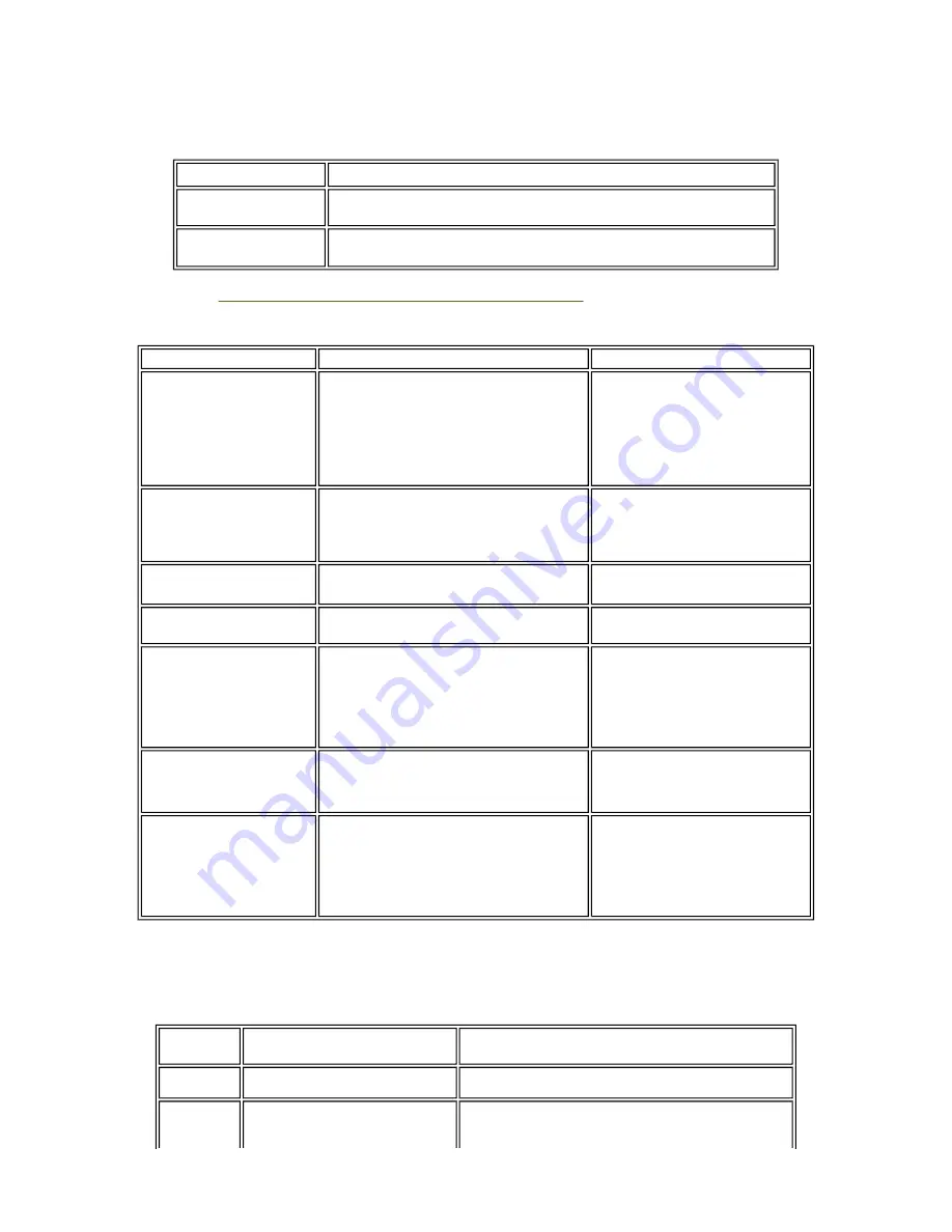
(3) Waste ink counter setting
When the logic board ass'y is replaced, reset the waste ink counter. In addition, according to the waste ink amount,
replace the waste ink absorber (ink absorber kit). The standard amount for waste ink absorber replacement is given
in the table below.
*1: Check the waste ink amount by service test print or EEPROM information print.
[See 3.3. Adjustment / Settings, (5) Service mode, for details.]
(4) User mode
<Standalone printer operation>
1) Turn on the printer.
2) Press and hold the Resume/Cancel button until the Power LED blinks in green the specified number of times
listed in the table below, and release it. The operation starts.
Waste ink amount
*1
Ink absorber kit replacement
Less than 7%
Not required.
7% or more
Required.
Function
Procedures
Remarks
Print head manual cleaning
- Cleaning both black and color:
See "Standalone printer operation" below.
- Cleaning black or color separately, or both
black and color:
Perform from the printer driver
Maintenance tab.
Print head deep cleaning
- Cleaning black or color separately, or both
black and color:
Perform from the printer driver
Maintenance tab.
Paper feed roller cleaning
See "Standalone printer operation" below.
Nozzle check pattern
printing
See "Standalone printer operation" below.
Also available from the printer
driver Maintenance tab.
Print head alignment
See "Standalone printer operation" below.
In Custom Settings of the printer
driver Maintenance tab, manual
print head alignment (by selecting
the optimum values) as with the
conventional models can be
performed.
Bottom plate cleaning
Perform from the printer driver
Maintenance tab.
Cleaning of the platen ribs
when the back side of paper
gets smeared.
Print head replacement The print head is replaceable at the
same position as for ink tank
replacement. (Open the access cover.
When the carriage stops at the center,
the print head can be replaced.)
Power LED
blinking
Operation
Remarks
1 time
Print head manual cleaning
2 times
Nozzle check pattern printing
Set a sheet of plain paper (A4 or letter) in the ASF or
the cassette (according to the Paper Feed switch
1-22
Summary of Contents for iP4200 - PIXMA Photo Printer
Page 5: ...Part 1 MAINTENANCE ...
Page 19: ...To the top Part 1 3 REPAIR 3 1 1 14 ...
Page 25: ...1 20 ...
Page 26: ...2 CL base CL gear 3 PR shaft LF roller bushing To the top Part 1 3 REPAIR 3 3 1 to 2 1 21 ...
Page 35: ...Part 2 TECHNICAL REFERENCE ...
Page 39: ...3 PRINT MODE 3 1 Resolution 1 Normal color printing 2 Grayscale printing 2 4 ...
Page 47: ...Part 3 APPENDIX ...
Page 48: ...1 BLOCK DIAGRAM 1 1 PIXMA iP4200 To the top Part 3 1 BLOCK DIAGRAM 3 1 ...


